Structural Implications Can Monopoles Bear the "Weight" of AI?

The telecommunications industry stands at the precipice of a fundamental transformation. As 5G matures and the vision of 6G takes shape, the network edge is becoming intelligent. The future is not merely about connectivity—it is about computation at the edge, where AI inference happens milliseconds from the user, enabling autonomous systems, immersive reality, and real-time industrial control. This vision demands that processing power migrates from distant cloud data centers to the very base of the tower. But this raises an urgent structural question: Can today's slender monopoles bear the weight of tomorrow's AI?


monopole towers


The New Weight: Edge Computing's Structural Demand

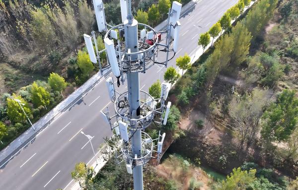
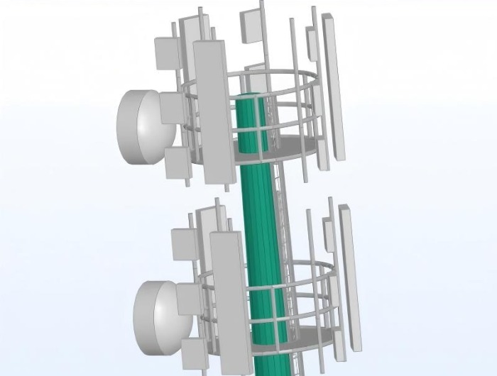
The integration of edge computing infrastructure into tower sites represents a paradigm shift in loading conditions. Traditional tower-mounted equipment—antennas, remote radio units (RRUs), and microwave dishes—is measured in kilograms. A typical 5G Massive MIMO antenna weighs 40-47kg . A full complement of sector antennas might total 200-300kg per platform.

Edge computing is different. It requires physical infrastructure: servers, storage, power distribution, and cooling systems. These are not lightweight appendages; they are substantial installations that, in a traditional data center context, demand floor loading capacities of 16 kN/m² or more . This figure—equivalent to approximately 1,600 kg per square meter—is not arbitrary. It reflects the weight density of fully populated server racks, battery backups, and the structural frames that support them.

For a monopole tower, this presents an unprecedented challenge. The question is not whether the tower can support a few additional kilograms—it is whether its foundation, shaft, and connection points can bear the concentrated weight of a micro data center at its base or, in more aggressive designs, mounted on its shaft.


Existing Capacity: The Monopole's Load Envelope

To understand the gap, we must first understand what today's monopoles are designed to carry. The loading capacity of a monopole depends critically on its height and structural design :


Tower Height Class Typical Equipment Load Capacity
Under 100 feet (30m) 500-1,000 lbs (227-454 kg)
100-150 feet (30-45m) 1,000-2,000 lbs (454-907 kg)
Over 150 feet (45m+) 2,000-5,000+ lbs (907-2,268 kg)
monopole towers

Extra-heavy-duty towers, specially engineered for extreme loads, can be rated for over 10,000 lbs (4,500 kg) . These capacities, however, assume that loads are distributed appropriately—typically antenna masses mounted on platforms along the upper shaft, with their weight transferred through the structure to the foundation.

The key observation is that even the largest monopoles have total equipment load capacities measured in thousands of kilograms—not tens of thousands. A fully equipped edge micro data center, with its servers, power systems, and thermal management, could easily consume 30-50% or more of a medium tower's total capacity before any antennas are installed.


The Structural Loading Gap: Comparing Requirements

The disparity between traditional antenna loads and edge computing requirements becomes stark when expressed in engineering terms.

Traditional Antenna Loads:

  1. · Distributed along upper shaft (favorable for moment distribution)

  2. · Low mass density per unit area

  3. · Dynamic wind loads dominate over static weight

  4. · Point loads manageable through localized reinforcement

Edge Computing Loads:

  1. · Concentrated at base or lower shaft (more favorable location, but high magnitude)
  2. · High mass density requiring substantial floor space
  3. · Static gravity loads dominate structural demand
  4. · Requires dedicated support platform with load distribution

monopole structures


A typical edge data center module, even in compact form factors, might impose a base area load of 5-10 kN/m²—lower than a core data center's 16 kN/m², but still an order of magnitude higher than the distributed loads from antenna platforms . For a tower with a base diameter of perhaps 1-2 meters, the available footprint is limited, concentrating these loads further.


The Foundation Question

The most critical structural element for bearing additional weight is not the tower shaft—it is the foundation. Monopole foundations are typically designed as rigid concrete piers or drilled shafts, sized to resist overturning moments from wind and the tower's self-weight .


monopole mast


Adding a multi-ton edge computing load at the base fundamentally alters the foundation's demand:

  1. · Increased compressive stress on the concrete and soil
  2. · Potential settlement if soils are compressible
  3. · Changed load eccentricity affecting moment distribution

Foundations are the most expensive and least accessible part of a tower to modify. A monopole designed without margin for significant additional base weight may face a hard constraint: the foundation cannot safely carry more load, regardless of what the shaft can support.


Reinforcement Strategies: Raising the Capacity Ceiling

For towers with structural margin—or for those where the foundation can accommodate additional load—several reinforcement strategies exist to increase shaft capacity.

1. External Steel Reinforcement (Field-Applied)

A patented method involves attaching vertical flat bars to the tower's exterior using one-sided bolts . These bars, typically steel, are installed continuously up the tower length, with joining plates connecting sections. The reinforcement works by sharing bending moments, effectively increasing the section modulus of the tower. This approach can be targeted to specific zones where additional equipment will be installed .

2. Carbon Fiber Reinforced Polymer (CFRP) Wrapping

Research at North Carolina State University has demonstrated that high-modulus carbon fiber polymers can increase monopole flexural capacity by 20-50% . This technique involves bonding CFRP sheets or strips to the tower's exterior, adding strength and stiffness with minimal weight penalty. The CFRP works compositely with the steel, resisting tensile stresses and delaying yielding. For towers where weight addition is the primary concern, CFRP offers an elegant solution .

3. Internal Stiffening and Bracing

For multi-sided monopoles, internal diaphragms or bracing can be added to increase local stability and global stiffness. This is most feasible during manufacturing but can be retrofitted in some designs.


monopole mast


Design Standards: Built for Today, Not Tomorrow

Current design standards for monopole towers—whether Eurocode , TIA , or GB standards —are focused on traditional telecommunications loads. Eurocode EN 1993-3-1 provides specific guidance for towers and masts, but its load combinations assume antenna and wind loads as the primary drivers . The safety factors embedded in these standards (typically 1.5-2.5 for ultimate loads) provide some margin, but this margin was never intended to accommodate an entirely new class of equipment .

The TIA has recently updated its data center standard (TIA-942) to address edge computing, recognizing that "data processing is increasingly happening at the Edge" and that "data- and compute-intensive AI applications require... significantly higher cabling and rack power densities" . However, this standard applies to the data center facility itself—not to the tower that must support it. A new class of design standard is needed, one that bridges telecommunications tower engineering and data center facility requirements.


Designing for the AI Era: New Monopole Specifications

For new deployments where edge computing integration is anticipated, the design must evolve:

  1. Increased Base Strength: Specify thicker steel in lower sections and larger base plates to accommodate concentrated loads.

  2. Integrated Equipment Platforms: Design the tower with dedicated structural supports for edge computing modules, integrated into the initial foundation design.

  3. Higher Safety Factors: Consider increasing the ultimate load safety factor beyond the standard 1.5-2.5 to provide margin for unknown future equipment .

  4. Modular Foundation Design: Size foundations with reserve capacity for additional dead load, anticipating that the tower's function may evolve over its 30-50 year lifespan.


Conclusion: The Structural Crossroads

The convergence of edge AI and telecommunications infrastructure presents the tower industry with a fundamental challenge. Today's monopoles, engineered for the relatively modest loads of antennas and RRUs, were not designed to host micro data centers. Their load capacities—ranging from 500 to 5,000 pounds—are measured in the same order of magnitude as the equipment they may soon be asked to support .

monopole steel tower

The path forward is not binary. Many existing towers can be reinforced through external steel members or advanced composites like CFRP, achieving 20-50% capacity increases . Foundations, however, remain the critical constraint—once poured, they are difficult and expensive to upgrade.

For new deployments, the message is clear: design for the AI era from day one. Specify higher-grade steels, increase base section thickness, and—most critically—pour foundations with reserve capacity for the unknown computational loads of tomorrow. The tower that hosts both antennas and AI will be the most valuable asset in the network. The question is whether today's monopoles are ready to bear that weight.


 Learn more at   www.alttower.com


Contact Us


READ MORE >

The Engineering Principles Behind 200m+ Guyed Communication Towers

In the relentless pursuit of expansive wireless coverage—for broadcasting, long-haul microwave links, or next-generation mobile networks—height is the ultimate asset.

guyed mast tower


It extends line-of-sight, clears terrain obstacles, and maximizes the economic value of a single site. However, for traditional self-supporting towers (monopoles or lattice), increasing height incurs a crippling economic penalty: material costs and foundation demands escalate exponentially. Beyond approximately 150-180 meters, the conventional paradigm breaks. This is where the guyed mast tower asserts its engineering and economic supremacy. By masterfully leveraging tensioned cables, it defies gravity not through brute mass, but through intelligent force distribution, fundamentally altering the relationship between height and cost for structures reaching 200, 300, and even 400 meters.

This blog deconstructs the core principles that allow guyed towers to achieve extreme heights with remarkable material economy.


The Cost-Height Conundrum: Why Self-Supporting Towers Hit a Wall

For a self-supporting tower, every additional meter of height must resist increasing overturning moments from wind. This resistance is provided solely by the tower's own bending stiffness and the foundation's ability to resist uplift. The result is a cubic relationship between height and material requirement. Doubling the height of a freestanding tower typically requires approximately eight times the material in the lower sections to maintain stability. Foundations become massive, deep-piled structures to prevent tipping. This makes self-supporting designs beyond 180-200m prohibitively expensive and logistically daunting.

guyed wire tower


The Guyed Mast Paradigm: Replacing Bending with Tension

The guyed mast inverts this problem. It is a slender, vertical column (the mast), stabilized not by its own girth, but by a system of high-strength steel guy cables anchored to the ground at radial distances. This system transforms the primary structural action from bending (inefficient) to axial compression and tension (highly efficient).


  1. · Load Transformation: When wind pushes against the mast, it attempts to bend it. The guy cables on the leeward side resist this motion by going into tension. This tension pulls the mast back toward vertical, while the windward cables slacken slightly. The mast itself primarily experiences axial compression, a load case where steel performs with exceptional efficiency.

  2. · The Power of Pre-Tension: The cables are not installed slack. They are pre-tensioned during erection to a calculated load. This initial tension ensures all cables remain taut under varying wind directions, eliminating destructive dynamic slack-tighten cycles that cause fatigue. Pre-tension also increases the system's natural frequency, improving its dynamic stability.


Core Engineering Principles Enabling Economic Height

1. Material Efficiency and Optimal Force Resolution
The mast can be an incredibly slender steel tube or lattice section because it does not need massive bending strength. Its primary job is to carry its weight and the equipment load as a column. The immense lateral wind force is resolved into manageable axial forces: compression in the mast and tension in the cables. High-strength steel cable, with a tensile strength far exceeding that of structural steel used in compression, handles this tension with minimal material. This separation of functions—compression vs. tension—allows each material to be used where it performs best, leading to a structure that is often less than half the weight of an equivalent-height self-supporting tower.

guyed wire tower

2. The Geometry of Stability: Anchor Radius and Guy Levels
The system's stiffness and economy are dictated by geometry.

  1. Anchor Radius: The distance from the mast base to the ground anchors. A larger radius allows the guy cables to act at a more favorable angle, reducing the tension required in the cables to counteract a given wind moment. This is a key economic lever.

  2. Multiple Guy Levels: Tall masts employ several sets of guy cables attached at different heights. This breaks the mast into a series of shorter, effectively braced columns, preventing global buckling and minimizing mast diameter. The optimal number and spacing of guy levels are calculated to minimize total material (mast + cable) cost.

3. Foundation Simplification: From Uplift to Gravity
This is a transformative cost advantage. A self-supporting tower foundation must be designed as a moment-resisting system, fighting enormous uplift and overturning forces with deep piles or massive concrete counterweights. A guyed mast foundation is simplified:

  1. Mast Foundation: Primarily carries a straightforward vertical compressive load (the weight of the structure). It is a simple slab or pile cap.

  2. Anchor Foundations: These are designed to resist pure vertical uplift from the cable tension. While significant, designing for pure uplift using dead weight (concrete blocks) or rock anchors is fundamentally simpler, requires less complex reinforcement, and is far more cost-effective per kilonewton of resistance than a moment-resisting foundation.

4. Aerodynamic and Dynamic Mastery
At extreme heights, dynamic response is critical.


  1. Aerodynamic Damping: The system has inherent damping. Energy from wind gusts is dissipated through slight, elastic stretching and vibration of the long cable runs.

  2. Avoiding Resonance: The fundamental natural frequency of a well-designed guyed mast is typically very low (e.g., 0.2-0.5 Hz), safely below the frequency of vortex shedding from the slender mast and the forcing frequencies of wind turbulence. Supplemental dampers (e.g., Stockbridge dampers on cables) can be added to suppress specific wind-induced vibrations.


guyed wire tower


Breaking the Linear Cost-Height Relationship

The combined effect of these principles is a dramatic flattening of the cost curve. Where a self-supporting tower's cost escalates exponentially, the guyed mast's cost increases at a rate much closer to linear with height. The additional material for a taller guyed mast is primarily incremental: more length of the slender mast section and longer guy cables. The fundamental engineering components—the concept of load transfer via tension, the foundation types—do not change, allowing for scalable design.

Comparative Snapshot: 250m Tower


  1. · Self-Supporting Lattice Tower: Would require a massive, tapered lattice base with enormous member sizes, a extraordinarily complex and deep foundation system, and total steel weight potentially exceeding 1,500 tons.

  2. · Guyed Mast: Would employ a relatively uniform, slender tubular mast (perhaps 2-3m diameter), 3-4 levels of guy cables, and a set of gravity block or anchor foundations. Total steel weight might be under 500 tons. The cost difference can be a factor of 2-3x in favor of the guyed solution.


guyed wire antenna tower


Conclusion: The Intelligent Path to the Stratosphere

Guyed communication towers represent a triumph of principle-based engineering over brute force. By understanding and harnessing the efficient load-carrying mechanisms of tension and compression, and by using the ground itself as a key structural component via anchors, they solve the problem of extreme height in the most materially economical way possible.

They are not suitable for every site—requiring significant land for anchor radii—but where space allows, they are the undisputed, most economical solution for piercing the 200-meter barrier and beyond. In defying gravity to connect the world, they prove that the most powerful engineering isn't about using more, but about using force more intelligently. For reaching the skies in pursuit of coverage, the guyed mast remains the most rational, gravity-defying choice.


 Learn more at   www.alttower.com


Contact Us

READ MORE >

The Resort Connectivity Solution Why Luxury Hotels Choose Palm and Pine Towers

In the world of luxury hospitality, every detail matters. The sweeping ocean view, the manicured golf course, the infinity pool perched above a tropical forest—each element is curated to create an experience of effortless beauty. Yet today’s guests arrive with an expectation that challenges this aesthetic perfection: flawless 4G, 5G, and Wi-Fi connectivity. The paradox of modern luxury is that guests demand to be simultaneously present in paradise and connected to the world. For resort owners, the solution lies not in hiding infrastructure, but in transforming it into part of the landscape itself. Enter the camouflage tree tower—a palm for the beachfront, a pine for the mountains—that seamlessly merges connectivity with the art of hospitality.


palm tree tower


The Resort Challenge: Connectivity Without Compromise

Luxury resorts face a unique infrastructure dilemma. Their properties are often located in precisely the places where conventional towers are least welcome: pristine coastlines, forested hillsides, and protected landscapes. Yet their guests, paying premium rates, expect uninterrupted service.

A guest checking into a five-star beach resort expects to stream, share, video call, and conduct business from their suite or sun lounger. A golfer on the 14th fairway needs reliable coverage to manage work calls between swings. A family exploring the resort grounds wants their children to stay connected while playing.


The traditional solution—a standard telecommunications tower—is unacceptable. It disrupts sightlines, clashes with architectural themes, and diminishes the very natural beauty that commands premium rates. The modern solution is infrastructure that serves without intruding: palm trees that transmit, pines that perform.


Palm and Pine: Site-Specific Design Philosophy

The choice between palm and pine is not merely aesthetic; it reflects the resort's geography and architectural context.

The Palm Tower: Coastal and Tropical Elegance

Palm towers are the quintessential solution for beachfront resorts, island properties, and coastal developments. Their slender trunks and graceful fronds harmonize with natural palm groves, making them virtually indistinguishable from living trees. Advanced manufacturing uses fiber-reinforced polymer (FRP) for fronds and trunk cladding, with fronds individually hand-painted to match local species. The result is a structure that appears to sway with the trade winds while providing robust connectivity.

For golf courses, palm towers offer dual functionality. Positioned strategically, they can serve as both hazard markers and coverage nodes—blending into the landscape while ensuring golfers remain connected for reservations, pace-of-play tracking, and emergency communication.

pine tree tower

The Pine Tower: Mountain and Forest Integration

For mountain resorts, alpine lodges, and forest retreats, the pine tower is the natural choice. Tall, tapered, and authentically textured, these structures mimic native conifers with remarkable fidelity. The trunk is clad in bark-textured panels cast from real tree molds, while branches are arranged in natural, asymmetric patterns that avoid the "lollipop" look of early designs.

These towers are particularly valuable in ski areas, where reliable coverage is a safety necessity. Guests on the slopes, families at the base lodge, and event planners coordinating weddings


The Value Proposition: Beyond Connectivity

For resort owners and developers, the decision to invest in camouflage towers is driven by a clear economic and experiential calculus.

1. Guest Experience: The Ultimate Differentiator
In the luxury segment, guest experience is paramount. A resort with poor connectivity faces negative reviews, frustrated guests, and diminished return visits. A resort with invisible but flawless coverage delivers a seamless experience that guests remember—without remembering why. The infrastructure disappears, allowing the beauty of the property to take center stage.

2. Property Value: Aesthetic Integrity as an Asset
Real estate value in luxury hospitality is intrinsically tied to aesthetics. A property marred by visible industrial towers loses its premium positioning. Camouflage towers protect that value. By maintaining unobstructed views and preserving landscape integrity, they ensure the property remains as photogenic in marketing materials as it is in person.

palm tree tower

3. Operational Efficiency: Staff and Management Connectivity
Beyond guest services, resorts themselves depend on reliable connectivity. From reservation systems and housekeeping coordination to security monitoring and emergency response, seamless coverage improves operational efficiency. Camouflage towers support these internal networks without compromising the guest experience.

4. Event and Wedding Revenue
Many resorts derive significant revenue from weddings, corporate retreats, and special events. These gatherings demand reliable connectivity for streaming, social sharing, and coordination. A property with robust, aesthetically integrated coverage can market this capability as a premium feature.


Case Examples: Integration in Practice

While specific projects often remain confidential due to resort branding sensitivities, the patterns of successful deployment are clear:

  1. Coastal Resort in the Caribbean: A 30-meter palm tower near the main pool area supports 5G coverage across the property. The tower is sited among existing coconut palms, with frond density adjusted to match the surrounding grove. Equipment cabinets are housed in a "dead frond skirt" at the base—a detail that enhances realism while concealing infrastructure.
  2. Mountain Resort in the Alps: A pine tower at mid-mountain provides coverage for both winter sports and summer hiking trails. The tower's height is limited to remain below the treeline when viewed from the valley, preserving the pristine silhouette of the peak.
  3. Golf Course Community in Florida: Multiple palm towers along the fairways serve dual purposes: they provide coverage for golfers and guests while functioning as visual landmarks that enhance course navigation.

Technical Considerations for Resort Deployments

Successful resort installations require careful attention to several factors:

Height Optimization: Towers must be tall enough to clear tree canopies and provide adequate coverage but not so tall as to dominate the landscape. Typical heights for resort applications range from 15 to 30 meters, with custom heights available for specific site conditions.

Load Capacity: Resorts often require multi-operator hosting to accommodate guests from various carriers. The camouflage structure must be engineered to support the combined weight and wind load of multiple antenna arrays.


palm tree tower


Environmental Compliance: Siting within protected coastal zones or forested areas requires rigorous environmental assessment. Experienced manufacturers work with local authorities to ensure compliance with all permitting requirements.

Long-Term Durability: Resort investments are long-term. Quality camouflage materials are rated for 20-30 years of UV exposure, with UV-stabilized polymers and durable bark coatings that resist fading, cracking, and degradation.


The ROI of Invisible Infrastructure

For resort owners, the return on investment in camouflage towers is measured not only in connectivity but in preserved value:

  1. · Premium room rates justified by uninterrupted service

  2. · Higher occupancy driven by positive reviews and word-of-mouth

  3. · Event bookings enabled by reliable coverage

  4. · Asset preservation maintaining the property's visual integrity


A property that invests $150,000 in a camouflage tower may recoup that investment many times over through enhanced guest satisfaction and the ability to command premium pricing.


Conclusion: The Future of Resort Connectivity

As guest expectations for connectivity continue to rise, and as 5G networks demand greater infrastructure density, the pressure to deploy towers in sensitive locations will only intensify. Luxury resorts that embrace camouflage technology are not merely solving a technical problem—they are making a strategic investment in their brand, their guest experience, and their long-term value.

The palm that provides coverage, the pine that performs—these structures represent the perfect synthesis of engineering and artistry. They prove that in the world of luxury hospitality, the best infrastructure is the infrastructure no one notices, quietly ensuring that paradise remains perfectly connected.


palm tree tower

READ MORE >

Why 100m+ Guyed Towers Dominate Modern Wind Measurement Campaigns

The wind energy industry is engaged in a quiet but relentless race upward. A decade ago, a 70-meter wind turbine was considered substantial. Today, 100-meter hub heights are standard, and turbines reaching 150 meters and beyond are increasingly common. For developers planning multi-million dollar wind farms, the stakes are enormous: a 10% error in wind speed assessment can translate to 30% variance in energy production estimates—and millions in revenue uncertainty. The foundation of accurate wind resource assessment is the meteorological (met) tower, which must rise to at least the hub height of the proposed turbines. As turbines climb, so must the towers that measure the wind. In this pursuit of height, the guyed lattice tower has emerged as the undisputed industry standard.


wind measurement met tower


The Height Imperative: Matching Turbine Hub Heights

Wind speed increases with elevation—a phenomenon known as wind shear. But this relationship is not linear or universal. It varies by terrain, atmospheric stability, and local geography. To accurately predict energy production, developers must measure wind speed at the actual height where turbines will operate.

Modern utility-scale turbines routinely feature hub heights of 100 to 160 meters. Offshore turbines and next-generation onshore models push toward 200 meters. A met tower that measures only at 60 or 80 meters forces developers to extrapolate wind speeds upward using theoretical models—models that can introduce unacceptable uncertainty into multi-million dollar investment decisions.

The industry standard, therefore, has become 100-meter met towers for onshore wind development, with taller structures specified for projects with higher hub heights or complex terrain.


The Structural Challenge: How to Reach 100+ Meters

Reaching 100 meters with a self-supporting structure is possible but economically punishing. A self-supporting lattice tower at this height requires substantial steel in its base sections—the cubic relationship between height and material demand drives costs exponentially upward. Foundations become massive concrete blocks or deep pile systems designed to resist enormous overturning moments.

The guyed tower solves this problem through a fundamental shift in structural behavior. Instead of resisting wind forces through the tower's own bending strength, it transfers lateral loads into tension in the guy cables and compression in the slender mast. This separation of function allows the mast to be remarkably lightweight—a uniform cross-section rather than a dramatically tapered base.

Comparative Material Efficiency

For a 100-meter tower:

  1. Self-supporting lattice: Requires substantial steel in base sections, often 50-80 tons total.

  2. Guyed lattice: A slender mast with 3-4 levels of guy cables, total steel weight often 15-25 tons—a 50-70% reduction.


This material efficiency translates directly to fabrication, transportation, and installation savings.


wind measurement met tower


Technical Advantages of Guyed Towers for Wind Measurement

Beyond raw material economy, guyed towers offer specific advantages for met tower applications.

1. Minimal Flow Distortion
Wind measurement requires the sensing equipment to be placed in undisturbed airflow. A self-supporting tower, with its substantial cross-section and massive base, can create wake effects that distort readings from anemometers mounted on the structure. The slender profile of a guyed mast minimizes this flow interference, providing cleaner, more accurate data.

2. Adaptable Siting in Complex Terrain
Wind farms are often located in precisely the areas where self-supporting towers are hardest to erect: ridgelines, steep slopes, remote forested areas. Guyed towers, with their modular components and ability to be erected with smaller cranes or even helicopter assistance, adapt readily to challenging sites.

3. Lower Foundation Impact
The central foundation of a guyed tower carries primarily compression from the mast's weight. Three or four anchor foundations, spaced radially, resist cable tension. This distributed system requires less concrete volume and can often be installed with minimal earth disturbance—a significant advantage in environmentally sensitive areas or on rocky terrain where excavating a single massive foundation is impractical.

4. Reduced Visual Impact
For temporary measurement campaigns (typically 1-3 years), the visual footprint matters. A slender guyed tower is far less intrusive than a massive self-supporting structure, easing permitting in areas with aesthetic concerns.


guyed mast tower


Cost Economics: Breaking the Height-Cost Curve

The economic advantage of guyed towers at 100+ meters is decisive:


Height Self-Supporting Cost Guyed Tower Cost Ratio
60m Baseline Baseline 1:1
80m 2.0x 1.4x 1.4:1
100m 3.5x 1.8x 1.9:1
120m 5.5x 2.2x 2.5:1

(These ratios are illustrative; actual figures vary by location and design specifications.)

The cost differential widens with height because the self-supporting tower's material and foundation requirements escalate exponentially, while the guyed tower's cost increases at a rate much closer to linear.


Application: The Measurement Campaign Lifecycle

A typical wind measurement campaign follows a predictable pattern that aligns perfectly with guyed tower capabilities:

  1. · Site Selection: The tower must be positioned in the zone of intended turbine development, often on ridgelines or open terrain where self-supporting tower foundations would be most challenging.

  2. · Permitting: Guyed towers, with their lower visual impact and reduced foundation footprint, often secure approvals more quickly, especially in areas with scenic or agricultural protections.

  3. · Installation: The modular design allows for erection with smaller cranes. A 100-meter guyed tower can be installed in 3-5 days with a crew of 4-6, compared to 2-3 weeks for a self-supporting structure.

  4. · Measurement Period: Typically 12-24 months of continuous data collection, with anemometers mounted at multiple heights (often 40m, 60m, 80m, 100m, and sometimes 120m). Guyed towers accommodate instrument booms with minimal flow distortion.

  5. · Decommissioning: Once the wind farm is financed and construction begins, the met tower is removed. Guyed towers disassemble efficiently, leaving behind only the small anchor foundations, which can be removed or left with minimal land impact.


guyed mast tower


Conclusion: The Rational Choice for Wind Resource Assessment

As wind turbines continue their ascent toward 100, 120, and 150-meter hub heights, the measurement infrastructure must follow. The guyed lattice tower offers the optimal combination of height capability, cost efficiency, and measurement accuracy for modern wind resource assessment campaigns. Its material efficiency, logistical adaptability, and minimal flow distortion make it the industry standard for developers seeking to minimize uncertainty in their multi-million dollar investments.

For a project where a 10% error in wind speed means a 30% error in revenue, the ability to measure accurately at the correct height is not a luxury—it is a necessity. And for reaching those heights, the guyed tower remains the most rational, economical, and technically sound choice.

Keywords: Guyed Tower, Met Tower, Wind Measurement, Wind Resource Assessment, Hub Height, Lattice Tower, Wind Energy, Renewable Energy Infrastructure.


READ MORE >

Why Guyed Towers Dominate Ultra-Tall Communication and Broadcast Applications

In the hierarchy of telecommunication infrastructure, height is the ultimate differentiator. For broadcasters seeking to blanket entire regions with FM or TV signals, for long-haul microwave links requiring unobstructed line-of-sight, and for rural network operators aiming to cover vast territories with minimal sites, the ability to reach extreme altitudes is not a luxury—it is a fundamental requirement. When the target height exceeds 150 meters, the field of viable structural options narrows dramatically. And when it approaches 300 meters or more, one tower type stands alone as the undisputed champion: the guyed mast.

guyed mast tower


This blog presents a comparative analysis of tower types at ultra-tall heights, examining why guyed towers dominate the skyline where others cannot economically or technically follow.


The Height Threshold: Where Other Towers Stop

Every tower type has an inherent height ceiling, dictated by the laws of structural mechanics and economic reality.


Tower Type Typical Maximum Height Primary Limiting Factor
Monopole 60 meters (200 feet) Exponential increase in steel thickness and foundation size beyond this point 
Self-Supporting Lattice 200 meters Cubic relationship between height and material required for base sections 
Guyed Mast 600+ meters Land availability for anchor radius; structural capacity continues with linear cost scaling 

A monopole's single, tapered tube must resist all bending moments through its own flexural stiffness. Doubling its height typically requires eight times the material in the lower sections and a foundation of immense proportions. This is why monopoles are rarely specified above 60 meters .

Self-supporting lattice towers perform better, with their wide bases and triangulated frames distributing loads efficiently. However, they too face a harsh economic reality: the relationship between height and material consumption is nonlinear. A 200-meter lattice tower requires significantly more than twice the steel of a 100-meter version . Above this range, the structure becomes prohibitively massive.

Guyed towers break this paradigm entirely.


The Engineering Secret: Tension as the Primary Load Path

The guyed mast achieves its height dominance through a fundamental shift in structural behavior. Rather than resisting wind forces through bending—an inefficient use of steel—it transforms those forces into tension in the guy cables and compression in the slender mast .

  1. The mast carries primarily vertical loads: its own weight, the equipment, and the downward component of cable tension. It needs sufficient stiffness to resist buckling between guy levels, but it does not require the massive bending strength of a self-supporter.

  2. The guy cables, typically three or four sets arranged radially, resist the lateral wind forces. High-strength steel cable, with tensile strengths far exceeding structural steel, handles these forces with minimal material cross-section .

  3. The anchors transfer cable tension into the ground through gravity blocks or rock anchors, designed for pure uplift resistance rather than complex moment-resisting foundations .


This separation of function—compression in the mast, tension in the cables—allows each component to be optimized for its specific role. The result is a structure that can reach 600 meters or more with a total steel weight far less than a self-supporter of equivalent height .

guyed mast antenna tower


Economic Analysis: Breaking the Cost-Height Curve

The economic advantage of guyed towers at extreme heights is decisive. The cost of a self-supporting tower escalates exponentially with height; the guyed mast's cost escalates at a rate much closer to linear.


Material Costs

A guyed tower uses significantly less steel. The mast remains relatively uniform in cross-section throughout its height, and the cables add minimal material mass. For a 300-meter structure, the material savings compared to a self-supporting lattice tower can exceed 50% .


Foundation Costs

This is where the difference becomes stark. A self-supporting tower requires a single, massive foundation designed to resist enormous overturning moments. This often means deep piles, immense concrete volumes, and complex reinforcement. A guyed tower's central foundation carries only compression—a simple slab or pile cap. The anchor foundations, while multiple, are designed for pure uplift and are generally less expensive per unit of resistance . However, this advantage is location-dependent: rocky terrain can make excavating multiple anchor points costly .


Installation and Logistics

The lighter, modular components of a guyed mast are easier to transport to remote sites—a common requirement for rural broadcast applications . Erection is systematic: the mast is assembled in sections and raised while cables are progressively tensioned. While specialized, this process is well-established and predictable.


guyed wire tower


The Space Trade-Off: Why Guyed Towers Need Room

The primary drawback of the guyed tower is its land footprint. The guy anchors extend radially from the base, typically at a distance of 60-80% of the tower height . For a 300-meter tower, this means an anchor radius of 180-240 meters, requiring a substantial land area free of obstructions and buildings.

This is why guyed towers are the antithesis of urban infrastructure. In dense cities, where land is precious and zoning is strict, monopoles or self-supporting lattice towers are the only options . But in rural areas, on mountaintops, and in open plains—precisely where ultra-tall towers are most needed—land is available, and the guyed tower's space requirement becomes an acceptable trade-off for its height capability .


Application Scenarios: Where Guyed Towers Excel

The guyed mast is not a general-purpose solution; it is a specialized tool for specific, demanding applications :

1. Broadcasting (FM, TV, HDTV)
Broadcast signals require elevation to achieve line-of-sight coverage over large populations. A 300-600 meter guyed mast atop a hill or in a plain can serve an entire metropolitan region. The Senior Road Tower in Missouri City, Texas, standing at 601 meters, serves as the primary transmitting facility for nine FM radio stations . No other tower type could economically achieve this height with the necessary antenna capacity.

2. Long-Haul Microwave Relay
Microwave links require unobstructed paths between repeaters. In flat or gently rolling terrain, elevation is the only way to achieve this. Guyed towers provide the height needed to clear tree lines, buildings, and terrain features, enabling reliable backhaul over tens of kilometers .

3. Rural and Remote Coverage
For cellular coverage in sparsely populated areas, a single tall tower can replace multiple shorter structures . The guyed mast's cost-effectiveness at height makes it the preferred choice for network operators seeking to minimize site count and backhaul complexity.


4. Lightning Protection and Instrumentation
In industrial settings, guyed towers serve dual purposes as lightning masts for refineries, chemical plants, and other facilities requiring protection over large areas .


guyed wire tower


Comparative Summary: Guyed vs. Lattice vs. Monopole at 200m+


Parameter Guyed Mast Self-Supporting Lattice Monopole
Maximum Practical Height 600+ m  ~200 m  ~60 m 
Relative Steel Weight Low (baseline) 2-3x heavier Not feasible at this height
Foundation Complexity Moderate (multiple anchors) High (single massive base) N/A
Land Required Large (anchor radius) Moderate (base only) N/A
Installation Cost Moderate High N/A
Maintenance High (cable tension, anchors)  Moderate (joint inspection) N/A
Typical Applications Broadcast, long-haul microwave, rural coverage  Broadcast, cellular at moderate height Urban, suburban

Conclusion: The Rational Choice for Extreme Heights

When the requirement is to reach beyond 200 meters—into the realm where signals travel hundreds of kilometers and coverage spans entire regions—the engineering and economic debate converges on a single conclusion. The guyed mast is not merely an alternative; it is the only rational choice.

Its ability to transform wind forces into efficient tension loads, its linear cost scaling with height, and its proven track record in the world's tallest structures all point to its dominance. The Senior Road Tower  and countless others like it stand as testaments to a design philosophy that leverages the ground itself as a structural component.

For network planners facing the challenge of ultra-tall requirements, the decision framework is clear: if you have the land and need the height, the guyed tower delivers capability that no other structure can match at any price. It is, and will remain, the height champion of telecommunications infrastructure.


 Learn more at   www.alttower.com


Contact Us

READ MORE >

The Inner Workings of Stone Polishing Machines A Deep Dive into Their Principles

Stone polishing is a meticulous process that begins with the use of abrasive particles. These particles, ranging from coarse to fine, work their magic on the stone surface. Starting with the coarse ones, they gradually reduce the saw marks from previous cutting processes. For instance, in the rough - grinding stage, 50# - 300# diamond grinding blocks are used to clear the initial saw marks and improve the surface flatness.

As we move through the semi - fine grinding, fine grinding, and then to the precision - focused fine - grinding and polishing stages, the scratches become finer and finer until they're almost invisible. When the surface reaches a smoothness of about 110 microns deep, a beautiful mirror - like sheen emerges. Each stage plays a crucial role. Fine grinding reveals the natural patterns of the stone, making it look more vivid, while the polishing stage, with the help of special pads like animal - hair pads or nano - pads and polishing agents, can boost the gloss level to over 85 degrees, sometimes even reaching 90 - 100 degrees.


Physicochemical Principle
Stone polishing is not about using machines to grind the stone. When we polish stone, something important happens, especially when we go back and forth between polishing with water and without water. The stone and the polish we use have a kind of reaction. For example marble is a type of stone that has calcium carbonate in it. When marble meets the parts of the polish like fluosilicic acid or special silica polishes it makes a strong and shiny layer on the stone. This layer does two things for the stone. It makes the stone look really glossy. It helps the stone resist stains. So it is like we are putting a protective and shiny shield on the surface of the stone. Stone polishing and the special layer it makes are really good, for the stone. The. The polish work together to make the stone look great and last a long time.
Key Equipment Characteristics
Modern Stone Polishing Machines, those made for marble have some really cool features. The dual speed system is great because it lets you switch easily between using a lot of power to grind and going really fast to polish. These Modern Stone Polishing Machines are pretty heavy they weigh 250 kilograms and the grinding disc can handle a lot of pressure over 180 kilograms so you know it can grind really well.The grinding disc on these Modern Stone Polishing Machines can be sizes, like 4 inches, 8 inches and 10 inches and you can attach grinding blocks in different ways, which makes these Modern Stone Polishing Machines good for many tasks.Safety is very important so these Modern Stone Polishing Machines have things like voltage, protection, from leaks and a special spring to absorb shocks. Some nice Modern Stone Polishing Machines even have things that make them very easy to use, like adjusting the pressure automatically a laser to help you position things and a system to spray polishing liquid.
Influential Factors
The final polishing effect is affected by several factors. The mineral composition of the stone matters a lot. Stones with clay minerals or a loose structure, like the white - sand beige marble, find it difficult to achieve a high gloss. The type of polishing agent used also plays a crucial role. Dry polishing requires a high - concentration polishing agent, while wet polishing needs careful water - volume control. Additionally, the process parameters, such as pressure, rotation speed, and the compatibility of the grinding disc material, all directly impact the final gloss level.

In conclusion, Stone Polishing Machines, whether they're Granite Polishing Equipment or Marble Grinder and Polishers, use a combination of mechanical grinding and chemical enhancement to bring out the best in our precious stones. It's this intricate balance that gives stones their stunning, high - gloss finish.


READ MORE >

Cast vs. Flow Formed vs. Forged Wheels – Which One Should You Get?

Picking wheels can be confusing. Cast, flow formed, forged... what's the difference? And more importantly, which one is right for your car?

1. Cast Wheels – The Budget Pick

How they're made: Melt aluminum, pour into a mold, let it cool. 

  • The good:

Cheap to make, cheap to buy

Works fine for daily driving

  • The not-so-good:

Heavy – hurts performance and fuel economy

Metal structure is porous, more likely to crack under stress


2. Flow Formed Wheels – The Middle Child

How they're made:Start with a cast, then heat it up and spin it while rollers squeeze and stretch the barrel. This makes the metal denser and stronger.

  • The good:

Lighter and stronger than cast

Better value than forged

  • The not-so-good:

Barrel design is limited by the process

Still not as strong as forged


3. Forged Wheels – The Real Deal 

How they're made:Take a solid block of premium aluminum (6061-T6). Squeeze it with over 10,000 tons of pressure. Then CNC-machine it into a work of art.

  • The good:

Super strong: Hit a pothole? It might bend, but it won't shatter.

Super light: Less unsprung weight = better acceleration, braking, and handling.

Fully customizable: Want a specific offset or crazy spoke design? No problem.

Built to last: These wheels can outlive your car.

  • The not-so-good:

Costs more 

So... Why Go Forged?

Honest talk? Not everyone needs forged wheels.

  • But if you:

Want your car to feel more responsive

Care about every pound of unsprung weight

Push your car hard – track days, canyon runs, or just aggressive driving

Want wheels that look exactly how you want them to look

...then forged is worth every penny.


Here's what you get with our forged wheels:

✅ Stronger, lighter, faster – you'll feel the difference

✅ Better heat dissipation – your brakes will thank you

✅ Built to your specs – perfect fitment, no spacers, no compromises

✅ Investment piece – wheels you'll keep for years


Wheels are a big decision. We get it.

👉 Check out our forged wheel gallery

👉 Tell us what you drive – we'll help you find the perfect fit

Performance wheels

READ MORE >

Forged Wheel Warranty Explained What We Guarantee and How It Works

When purchasing custom forged wheels, understanding the forged wheel warranty is essential. At Rimpower Wheel, we provide a clear and structured warranty policy to ensure every customer can order with confidence.


In this article, we explain what is covered by our forged wheel warranty, how our production process reduces risk, and what you can expect after delivery.


1. Built on Verified Design Before Production


Every order starts with a 3D technical drawing. Before production begins:


- The customer reviews and confirms all specifications  

- Our engineering team double-checks fitment, size, offset, and PCD  


Production only starts after full confirmation. This process ensures accurate fitment and avoids installation issues.


2. Structural Warranty for Forged Wheels


We provide a structural warranty of up to 5 years or 100,000 kilometers (whichever comes first).


Our forged wheels are made from high-strength T6061-T6 aluminum, offering excellent durability and performance under normal driving conditions.


*Note: This warranty does not apply to extreme lightweight designs.*


3. Surface Finish Warranty for Forged Wheels


- Standard finish: 12 months warranty  

- Chrome finish: 6 months warranty  


Our surface treatments are designed for durability, but environmental factors such as extreme weather or improper use may affect coating performance.


4. Fitment Guarantee and Replacement Support


We understand that fitment is critical. 


If installation issues occur due to design errors, we provide free replacement solutions. This ensures that customers receive wheels that match their vehicle perfectly.


5. Strict Material and Production Standards


All wheels are manufactured using forged aluminum blanks and processed with precise CNC machining.


Each step of production follows strict quality control standards to ensure consistency, safety, and long-term reliability.


6. What Is Not Covered


Like all automotive components, wheels can be affected by external factors. The warranty does not cover damage caused by:


- Improper transportation, storage, or installation  

- Overloading, accidents, or high-impact driving  

- Unauthorized modifications or welding  

  • Incorrect use of tires, bolts, or accessories  Rimpower Wheel Warranty


All wheels are shipped with a printed warranty card included in the package for reference.


Our goal is not only to manufacture high-quality forged wheels, but also to provide a reliable and transparent service process.


From design confirmation to warranty support, every step is built to reduce risk and ensure customer satisfaction.


If you are looking for custom forged wheels with dependable quality and support, feel free to contact us to start your project.


Explore our custom forged wheels for luxury vehicles → https://www.dhwheel.comhttps://www.dhwheel.com/category/luxury-wheel


READ MORE >

What Does 6061-T6 Forged Wheel Mean? The Engineering Behind the Performance

When shopping for high-performance wheels, you've likely come across the term "6061-T6 Forged." It’s often used as a badge of quality, but what does it actually mean for your driving experience? In simple terms, this specification defines the material, manufacturing process, and heat treatment that separate premium wheels from ordinary ones.


1. The Alloy: Why 6061?

The journey begins with 6061 aluminum, a aerospace-grade alloy known for its exceptional strength-to-weight ratio. By combining aluminum with silicon and magnesium, this material offers superior corrosion resistance and structural integrity. It’s the ideal foundation for a wheel that needs to be both lightweight and capable of handling extreme loads.


2. The Process: Forging

Forged wheel factory

This is where the magic happens. Unlike casting, which pours molten metal into a mold, forging starts with a solid billet of 6061 aluminum. Under thousands of tons of pressure, the metal's grain structure is compressed and aligned, resulting in a wheel that is denser, stronger, and more resistant to impact. As you can see in the image above, this is precision engineering at its finest—crafted right in our facility.


3. The Finish: T6 Heat Treatment

The "-T6" suffix refers to the thermal treatment applied after forging. Through solution heat treatment and artificial aging, the aluminum achieves peak hardness and tensile strength. This process ensures the wheel maintains its shape and performance under high heat and heavy stress—critical for track days or rough terrain.

A 6061-T6 forged wheel isn’t just a component; it’s an investment in performance and safety. By combining premium alloy, advanced forging, and precise heat treatment, these wheels reduce unsprung weight, improve handling, and offer unmatched durability. Whether you're building a race car or upgrading your daily driver, choosing 6061-T6 forged means choosing proven engineering.


READ MORE >

What is 2-piece forged wheel?

A two-piece forged wheel is a high-performance modular wheel constructed from two separate components: a center face (spokes and hub) and an outer barrel (rim). These components are typically manufactured from high-grade 6061-T6 aluminum using extreme heat and pressure to align the metal's grain structure, resulting in superior strength and lightweight characteristics compared to standard cast wheels. 

Two piece wheel structure

Construction and Components

Center Section (Face): Machined from a solid forged aluminum billet, this part houses the spokes and mounting surface.

Outer Barrel: A separately manufactured cylindrical piece that holds the tire in place.

Assembly Methods: The two pieces are permanently or semi-permanently joined through welding (creating a unified, rigid structure) or bolting with high-strength hardware. 

Black forged wheels

Key Benefits

Customization: Modular construction allows for a wider range of offsets, widths, and finishes than one-piece (monoblock) wheels. For instance, a customer can choose a custom-colored center with a polished or chrome barrel.

Repairability: If a wheel is damaged by a pothole or curb, the affected component (the barrel or the face) can often be replaced independently, saving up to 40% in total replacement costs compared to a one-piece wheel.

Performance: Forged 2-piece wheels are roughly 20–30% lighter than cast wheels, reducing unsprung mass to improve acceleration, braking distances, and handling agility.


Maintenance: They generally require less upkeep than 3-piece wheels because they have fewer joining points and seals to monitor.

Forged wheels for cars

READ MORE >