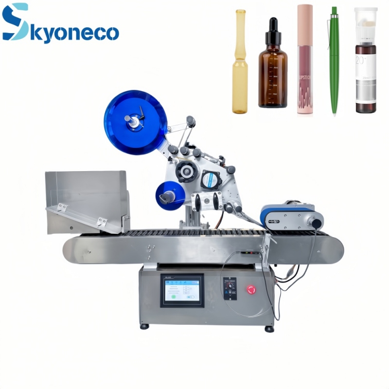
Reliable Corrosion-Resistant Chemical Pumps from Wolong Pump & Valve

For decades, Anhui Wolong Pump & Valve Co., Ltd. has been fully committed to the R&D, production and one-stop service of industrial chemical pumps. We have developed a comprehensive product line tailored to diverse and harsh chemical working conditions across multiple industries. Whether customers need to transport acid-base salt solutions, strong oxidants, organic compounds or other highly corrosive chemical media, our chemical pumps can maintain stable and continuous operation thanks to premium anti-corrosion materials and scientifically optimized structural design. Every product is manufactured in strict accordance with national and industrial quality standards. Before leaving the factory, all pumps undergo multiple rounds of performance testing, durability testing and leakage testing to eliminate potential operational risks. In addition to high-quality products, our professional technical team provides customized pump selection consulting services, analyzing on-site working conditions, medium characteristics, flow and head requirements for B-end industrial clients, so as to help every enterprise select the most cost-effective and matching fluid conveying equipment.


Among our products, the 25FSB-25 fluoroplastic centrifugal pump stands out as a classic model widely recognized by industrial users. This pump adopts high-performance fluoroplastic alloy as the material for all flow-passing components, which features outstanding resistance to strong acids, strong alkalis and various organic solvents.making it perfectly suitable for small and medium-sized fluid conveying scenarios in chemical plants, pharmaceutical factories, electroplating workshops, pesticide production lines and non-ferrous metal smelting enterprises. For small-batch medium transportation and circulating liquid delivery in laboratory and fine chemical industries, the 25FSB-25 pump has become the preferred equipment for countless enterprises due to its stable performance and easy maintenance.


Backed by more than 40 years of industry experience, Anhui Wolong Pump & Valve Co., Ltd. is China’s largest production base of fluoroplastic pump and valve products, a professional R&D team composed of senior engineers. Beyond the 25FSB-25 fluoroplastic centrifugal pump, we offer over 20 product series and more than 400 specifications of anti-corrosion pumps, including fluoroplastic magnetic pumps, self-priming pumps, vertical sump pumps and stainless steel centrifugal pumps, to cover the full-range fluid conveying demands of different industrial sectors.We always adhere to the business philosophy of technological innovation and quality priority, and keep upgrading our products and services to create greater value for industrial fluid transportation.Fluoroplastic Alloy Pump Factory

READ MORE >

Safety & Efficiency Professional Chemical Pump Manufacturer – Anhui Wolong Pump & Valve Co., Ltd.

As a professional manufacturer specializing in industrial fluid conveying equipment, Anhui Wolong Pump and Valve Co., Ltd. is committed to developing pumps with outstanding adaptability and intrinsic safety to harsh chemical conditions.To address core pain points such as medium corrosion, high energy consumption and unstable operation in chemical factories, our R&D team matches targeted fluoroplastic alloy, stainless steel and other anti-corrosion materials for different corrosive media including strong acid, strong alkali, toxic and volatile liquids. Every chemical pump leaving our factory will go through full hydraulic performance test, leakage inspection and continuous aging verification in our standardized testing workshop, strictly complying with national and international industrial production standards to eliminate hidden safety risks for long-cycle industrial operation. Our full product portfolio covers magnetic pumps, centrifugal pumps, self-priming pumps, vertical sump pumps and GF series fluorine lined pipeline pumps, covering all mainstream fluid transportation demands across petrochemical, pharmaceutical, chlor-alkali, rare earth smelting and wastewater treatment industries.


Take the classic 32GF-20 fluorine interlined vertical pipeline pump as a typical representative of our mature GF series product line. The 32GF-20 inline pump features vertical integrated structure with identical inlet and outlet flanges on one central line, requiring minimal installation space for compact workshop layouts; all wetted components are fully lined with F46 fluoroplastic alloy, capable of stably circulating hydrochloric acid, nitric acid, plating waste liquid and organic solvents without erosion damage. Its streamlined optimized flow channel design effectively cuts running noise and energy loss, perfectly matching small-flow dosing, circulating acid addition and waste liquid transfer procedures in electroplating workshops and pharmaceutical pilot production lines. Beyond standardized models like 32GF-20, Anhui Wolong Pump & Valve Co., Ltd. delivers exclusive customized fluid transfer solutions for enterprises with special working condition requirements. Our professional engineering team adjusts pump flow, head, motor explosion-proof grade and lining material configuration according to clients’ actual medium temperature, concentration, pipeline layout and production cycle demands. Chemical pump factory

READ MORE >

Why Is My W12 Rolling Machine Producing Uneven Cylinders?

One of the most common quality issues in plate rolling operations is the production of uneven cylinders, where the finished workpiece shows defects such as out-of-roundness, inconsistent diameter, tapering, edge distortion, or ovality.

For a W12 4-roll plate rolling machine, uneven cylinder formation usually does not result from a single fault. Instead, it is often caused by the interaction of machine geometry, hydraulic synchronization, material characteristics, process settings, and operator parameters.


Understanding the root causes is essential because even small deviations can lead to:

  •  Assembly problems
  • Welding difficulties
  • Structural stress concentration
  • Product rejection
  • Increased material waste

This technical guide explains the most common reasons for uneven cylinder formation and how to troubleshoot them effectively.


What Is an Uneven Cylinder?


An uneven cylinder refers to a rolled component whose geometry deviates from the intended cylindrical shape.

Common defects include:

Ovality

The cylinder diameter varies in different directions.


Tapering

One side has a larger diameter than the opposite side.


Barrel Shape

The center diameter differs from the edge diameter.


Flat Ends

Insufficient pre-bending leaves unformed edges.


Helical Distortion

The workpiece twists during rolling.


Main Causes of Uneven Cylinders in W12 Rolling Machines


1. Roll Misalignment


Roll alignment is one of the most critical factors in cylinder accuracy.

If the rolls are not parallel:

  • Bending force distribution becomes uneven
  • Material flow becomes asymmetrical
  • Diameter varies along the cylinder length


Possible Causes

  • Machine foundation movement
  • Mechanical wear
  • Improper installation
  • Maintenance errors


Inspection Method

Check:

  • Upper roll levelness
  • Side roll parallelism
  • Roll centerline deviation

Laser alignment systems are often used for high-precision inspection.


Recommended Solution

  • Recalibrate roll alignment
  • Adjust roll positioning parameters
  • Perform regular geometric inspection


2. Hydraulic Synchronization Errors


The W12 machine relies heavily on hydraulic synchronization for precise roll positioning.

Synchronization errors may create:

  • Unequal roll movement
  • Asymmetric pressure distribution
  • Uneven deformation


Common Causes

  • Hydraulic cylinder mismatch
  • Pressure instability
  • Valve response differences
  • Sensor deviation


Symptoms

  • One side rolls faster than the other
  • Uneven side roll movement
  • Variable cylinder diameter


Recommended Solution

Inspect:

  • Hydraulic pressure stability
  • Cylinder synchronization
  • Position sensors
  • Servo valve performance


3. Material Thickness Variation


Even when the machine operates correctly, inconsistent material thickness may cause rolling defects.


Example

Plate thickness:

  • Left side = 9.8 mm
  • Right side = 10.4 mm

The thicker region requires greater deformation force, resulting in:

  • Different rolling radii
  • Oval cylinders
  • Diameter variation


Recommended Solution

Before rolling:

  • Measure plate thickness at multiple locations
  • Verify material uniformity
  • Inspect supplier quality records


4. Material Yield Strength Variation


Material mechanical properties significantly affect rolling behavior.

Variations in:

  • Yield strength
  • Hardness
  • Residual stress
  • Heat treatment condition

may result in inconsistent deformation.


Example

Areas with higher yield strength:

  • Resist deformation
  • Produce greater springback

This may generate:

  • Uneven curvature
  • Local diameter differences


Recommended Solution

Use materials with:

  • Certified mechanical properties
  • Consistent batch quality


5. Incorrect Pre-Bending Parameters


Pre-bending strongly influences final cylinder geometry.

Insufficient pre-bending can create:

  • Flat ends
  • Edge mismatch
  • Diameter inconsistency


Common Operator Errors

  • Insufficient side roll movement
  • Incorrect pressure setting
  • Excessive rolling speed


Recommended Solution

Optimize:

  • Pre-bending stroke
  • Side roll position
  • Feed sequence


6. Improper Roll Pressure Distribution


Uneven force distribution creates non-uniform plastic deformation.

Possible causes include:

  • Hydraulic imbalance
  • Incorrect pressure settings
  • Mechanical wear


Engineering Effect

Unequal pressure:

F1≠F2

causes:

R1≠R2

Where:

  • F = rolling force
  • R = resulting radius


Recommended Solution

Calibrate:

  • Hydraulic system pressure
  • Pressure control valves
  • CNC compensation parameters


7. Residual Stress and Springback


Residual stress within the plate may significantly affect final shape.

Springback becomes more noticeable in:

  • High-strength steels
  • Stainless steel
  • Thick plates


Common Effects

  • Diameter increase after unloading
  • Uneven curvature
  • Distortion after welding


Recommended Solution

Apply:

  • Over-bending compensation
  • CNC springback correction
  • Multi-pass rolling strategy


8. Improper Feeding Alignment


Incorrect plate feeding causes uneven material movement.

Symptoms include:

  • Helical rolling
  • Tapered cylinders
  • Edge offset


Recommended Solution

Check:

  • Plate squareness
  • Feed positioning
  • Side support devices
  • Alignment indicators


9. Worn Rolls or Mechanical Components


Long-term operation may cause wear in:

  • Roll surfaces
  • Bearings
  • Shaft supports
  • Guide systems

Wear reduces rolling precision.


Inspection Items

Measure:

  • Roll diameter variation
  • Surface damage
  • Bearing clearance
  • Shaft runout


Recommended Solution

Replace worn components and perform periodic maintenance.


Troubleshooting Flow for Uneven Cylinders


Inspection Step

Check Item

Step 1

Material thickness consistency

Step 2

Roll alignment

Step 3

Hydraulic synchronization

Step 4

Pressure settings

Step 5

Pre-bending parameters

Step 6

Springback compensation

Step 7

Mechanical wear


Following a systematic process reduces troubleshooting time.


Preventive Measures for Stable Cylinder Quality


To improve rolling consistency:

Maintain machine calibration

Regularly verify:

  • Roll alignment
  • Position accuracy
  • Hydraulic synchronization


Establish material inspection procedures

Check:

  • Thickness
  • Yield strength
  • Surface condition


Optimize CNC programs

Modern CNC systems can automatically compensate for:

  • Springback
  • Material variation
  • Rolling sequence adjustments


Schedule preventive maintenance

Regular inspections reduce:

  • Mechanical wear
  • Hydraulic faults
  • Positioning errors


Why Choose ZYCO W12 Rolling Machines?


Modern ZYCO W12 4-roll plate rolling machines are engineered to minimize geometric variation and improve rolling consistency.

Technical advantages include:

  • Precision hydraulic synchronization
  • Advanced CNC compensation systems
  • High-rigidity frame structures
  • Intelligent diagnostic functions
  • High positioning accuracy

These features help manufacturers achieve stable, high-quality cylindrical forming with reduced operator dependency.


Conclusion


Uneven cylinders produced by a W12 rolling machine are usually caused by multiple interacting factors rather than a single fault.

The most common causes include:

  • Roll misalignment
  • Hydraulic synchronization errors
  • Material inconsistency
  • Improper pressure settings
  • Springback effects
  • Mechanical wear

A systematic troubleshooting approach combined with preventive maintenance and optimized CNC settings is essential for achieving high-precision cylindrical rolling results.


READ MORE >

ZYCO FAQ What Are the Common Safety Features on a W12 Plate Roller?

Safety is one of the most critical considerations in modern plate rolling operations. A W12 4-roll plate rolling machine generates extremely high forming forces and handles heavy metal plates, making operator protection and machine stability essential.

Modern W12 machines are therefore equipped with a wide range of mechanical, hydraulic, electrical, and CNC-integrated safety systems designed to reduce operational risks, protect equipment, and ensure compliance with industrial safety standards.

This article explains the most common safety features found on W12 plate rolling machines and their engineering functions in industrial production environments.


Why Safety Is Critical in Plate Rolling Operations

Plate rolling involves several potential hazards:

· High-pressure hydraulic systems

· Rotating rolls with strong pinch forces

· Heavy plate handling

· Sudden material movement

· Stored elastic deformation energy

Without proper protection systems, these risks may lead to:

· Operator injury

· Equipment overload

· Plate ejection accidents

· Hydraulic failures

· Production downtime

Modern W12 rolling machines are designed to minimize these risks through integrated safety engineering.


1. Emergency Stop (E-Stop) System

The emergency stop system is the most fundamental safety feature.

Function

When activated, the system immediately:

· Stops roll rotation

· Cuts hydraulic movement

· Interrupts electrical output

· Brings the machine into a safe state

Emergency stop buttons are typically installed at:

· Operator control panels

· Machine front and rear positions

· Remote control stations


Engineering Importance

The E-stop system minimizes injury risk during:

· Unexpected plate movement

· Operator entrapment

· Hydraulic malfunction

· Electrical faults

International safety standards generally require emergency stop circuits to use:

· Fail-safe design

· Redundant wiring

· Safety relays or safety PLCs


2. Overload Protection System

W12 plate rolling machines operate under extremely high rolling forces.

To prevent structural damage, machines include overload protection systems.


Hydraulic Overload Protection

The hydraulic system monitors:

· Cylinder pressure

· Hydraulic load levels

· Torque demand

If the force exceeds the machine limit:

· Hydraulic relief valves activate

· Pressure is released automatically

· Machine movement is restricted

This protects:

· Roll shafts

· Bearings

· Hydraulic cylinders

· Machine frame structure


3. Safety Interlock System

Safety interlocks prevent dangerous machine operations under unsafe conditions.

Typical interlock conditions include:

Unsafe Condition

Interlock Action

Guard open

Machine disabled

Hydraulic fault

Motion blocked

Electrical fault

Emergency shutdown

Roll synchronization error

Operation stopped


Purpose of Interlocks

Interlocks ensure that:

· Operators cannot access hazardous areas during operation

· Machine functions occur only in safe operating states

· Fault conditions do not escalate into accidents


4. Pinch Point Protection

One of the biggest hazards in plate rolling is the pinch zone between rolls.

Modern W12 machines reduce pinch risks using:

· Safety barriers

· Protective covers

· Distance guarding

· Controlled feed positioning


CNC-Controlled Speed Reduction

Some advanced systems automatically reduce rolling speed during:

· Plate feeding

· Edge alignment

· Initial pre-bending

This improves operator reaction time and reduces injury risk.


5. Hydraulic System Safety Features

The hydraulic system is a major source of stored energy and must be carefully protected.


Common Hydraulic Safety Components

Pressure Relief Valves

Prevent excessive hydraulic pressure buildup.


Hose Burst Protection

Stops uncontrolled movement if a hydraulic hose fails.


Hydraulic Locking Circuits

Maintain roll position during pressure fluctuations or power loss.


Oil Temperature Monitoring

Protects hydraulic components from overheating.


6. Electrical Safety Protection

Modern W12 machines use industrial-grade electrical protection systems.


Typical Features Include

· Circuit breakers

· Overcurrent protection

· Ground fault protection

· Motor overload protection

· Short-circuit protection


Safety PLC Integration

Advanced machines use Safety PLC systems to monitor:

· Emergency circuits

· Interlocks

· Sensor status

· Motion synchronization

Safety PLCs improve system reliability and diagnostic capability.


7. Roll Synchronization Monitoring

Inaccurate roll synchronization may create dangerous plate instability.

Advanced W12 machines monitor:

· Roll position deviation

· Hydraulic cylinder synchronization

· Motion feedback signals

If synchronization exceeds allowable tolerance:

· Machine movement stops automatically

· Alarm systems activate

This protects both operators and workpieces.


8. Plate Drop and Ejection Protection

Heavy plates may shift unexpectedly during rolling.

To reduce this risk, machines may include:

· Plate support arms

· Side support devices

· Anti-drop mechanisms

· Feeding tables

These systems improve stability during:

· Large-diameter rolling

· Thin plate processing

· Conical rolling operations


9. Safety Guards and Physical Barriers

Physical guarding is essential for isolating dangerous moving components.

Typical guarding systems include:

· Side covers

· Rear barriers

· Roll protection shields

· Maintenance access locks

Guard systems are designed to:

· Prevent accidental contact

· Restrict access to moving components

· Improve compliance with CE and ISO safety standards


10. CNC Safety Monitoring Functions

Modern CNC systems provide advanced safety diagnostics.


Common CNC Safety Features

Real-Time Alarm Monitoring

Displays abnormal operating conditions instantly.


Motion Limitation Control

Prevents dangerous roll travel beyond safe limits.


Automatic Fault Detection

Identifies:

· Hydraulic abnormalities

· Encoder failures

· Positioning errors

· Synchronization faults


Operator Permission Levels

Restricts unauthorized parameter modification.


International Safety Standards for Plate Rolling Machines

Professional W12 rolling machines are typically designed according to:

· CE Safety Standards

· ISO 12100 Machine Safety

· IEC Electrical Safety Standards

· Hydraulic Safety Regulations

Compliance improves:

· Workplace safety

· Machine reliability

· International market acceptance


Why Safety Engineering Matters in Modern Manufacturing

Modern fabrication facilities increasingly prioritize:

· Operator protection

· Production continuity

· Reduced downtime

· Regulatory compliance

Advanced safety systems help manufacturers achieve:

· Lower accident rates

· Reduced maintenance costs

· Improved operational stability


Why Choose ZYCO W12 Plate Rolling Machines?

Modern ZYCO W12 4-roll plate rolling machines are designed with integrated industrial safety systems for demanding production environments.

Key safety advantages include:

· Intelligent CNC safety monitoring

· Hydraulic overload protection

· Precision synchronization control

· Emergency shutdown systems

· High-rigidity machine structures

· CE-compliant safety design

These features help ensure safe, stable, and efficient rolling operations.


Conclusion

A modern W12 4-roll plate rolling machine incorporates multiple layers of protection, including:

· Emergency stop systems

· Hydraulic overload protection

· Electrical safety systems

· CNC-integrated monitoring

· Roll synchronization protection

· Physical guarding systems

Together, these technologies significantly reduce operational risks while improving production reliability and machine lifespan.

For manufacturers focused on industrial safety and long-term operational stability, selecting a properly engineered W12 rolling machine is essential.


READ MORE >

ZYCO FAQ What Is the Minimum Diameter a 4-Roll Machine Can Achieve?

The minimum rolling diameter of a 4-roll plate rolling machine is one of the most important technical parameters in plate forming applications. It directly affects whether a machine can produce small-diameter cylinders, tight-radius sections, or high-curvature components required in advanced fabrication industries.


However, the minimum achievable diameter is not determined by a single factor. It depends on the interaction between:

  • Roll geometry
  • Plate thickness
  • Material yield strength
  • Machine structure
  • Forming method
  • Residual springback characteristics

This article explains the engineering principles behind minimum rolling diameter calculation and the limitations of 4-roll plate rolling machines in real industrial applications.


What Does “Minimum Rolling Diameter” Mean?


The minimum rolling diameter refers to:

The smallest internal cylinder diameter that a rolling machine can form while maintaining acceptable geometric accuracy and material integrity.

This parameter is typically specified under standard conditions:

  • Mild steel material
  • Standard yield strength (~245 MPa)
  • Full-width rolling
  • Cold forming process


Why Minimum Diameter Matters


Smaller rolling diameters are required in applications such as:

  • Pressure vessel nozzles
  • Pipe sections
  • Heat exchanger shells
  • Ventilation ducts
  • Cone transitions
  • Compact cylindrical structures

Achieving small diameters requires significantly higher localized deformation, which increases the demands on machine rigidity and rolling force.


Main Factors Affecting Minimum Rolling Diameter


1. Upper Roll Diameter

The most critical factor is the diameter of the top roll.


Engineering Principle

A rolled plate cannot normally achieve a radius significantly smaller than the top roll radius without excessive deformation or instability.

In general:


Where:


Example

If the upper roll diameter is:

300 mm

Then the minimum rolling diameter is approximately:

330–450 mm

depending on material and thickness.


2. Plate Thickness

Thicker plates are more difficult to deform into tight radii.


Relationship

As thickness increases:

  • Required bending moment increases exponentially
  • Internal stress increases
  • Springback becomes larger

This increases the achievable minimum diameter.


Engineering Trend


Plate Thickness

Minimum Achievable Diameter

Thin plate

Smaller diameter possible

Thick plate

Larger minimum diameter


3. Material Yield Strength


Higher-strength materials resist deformation more strongly.

Examples:


Material

Rolling Difficulty

Rolling Difficulty

Mild steel

~245 MPa

Low

Stainless steel

~520 MPa

Medium

High-strength steel

>700 MPa

High


Higher yield strength causes:

  • Increased springback
  • Higher forming force requirements
  • Larger minimum achievable diameter


4. Side Roll Geometry and Movement


In a W12 4-roll machine:

  • Side rolls control plate curvature
  • Roll positioning accuracy directly affects small-radius forming

Machines with:

  • Independent hydraulic side roll control
  • High-precision synchronization
  • CNC compensation systems

can achieve tighter diameters more accurately.


5. Residual Springback


Springback occurs when the material partially returns toward its original shape after unloading.

Important Impact

For small-diameter rolling:

  • Springback becomes more significant
  • Final diameter may increase after release

Therefore, operators must apply:

  • Over-bending compensation
  • CNC correction algorithms

to achieve the target diameter.


Simplified Engineering Estimation Formula


A practical estimation formula used in plate rolling is:

hydraulic rolling machine 

Where:


Typical values:


Material Type

k Value

Mild steel

20–30

Stainless steel

30–40

High-strength steel

40–50


Example Calculation


Given

  • Mild steel plate
  • Thickness: 10 mm
  • Coefficient: 25

Estimated minimum diameter:


This provides a preliminary engineering estimate.


Difference Between Theoretical and Actual Minimum Diameter


In practice, actual rolling diameter is influenced by:

  • Operator experience
  • CNC control precision
  • Plate edge condition
  • Friction coefficient
  • Machine wear condition

Therefore:

Actual achievable diameter is often slightly larger than theoretical calculations.


Pre-Bending Limitations


One critical limitation is pre-bending.

Even if the machine can roll a small diameter in the center section:

  • Plate edges may remain flat
  • Additional calibration may be required

4-roll machines reduce this issue because they support:

  • Continuous clamping
  • Improved edge pre-bending capability


Advantages of 4-Roll Machines in Small Diameter Rolling


Compared to 3-roll machines, 4-roll systems offer several technical advantages:


Better Plate Stability

Continuous clamping reduces slippage during high-curvature forming.


Higher Precision

Independent roll control improves curvature consistency.


Improved Pre-Bending

Smaller flat-end sections can be achieved.


Better CNC Integration

Automated compensation improves small-radius accuracy.


CNC Compensation for Small Diameter Rolling


Modern CNC systems can automatically adjust:

  • Roll position
  • Pressure distribution
  • Over-bending amount

based on:

  • Material database
  • Plate thickness
  • Target diameter

This greatly improves repeatability for tight-radius rolling.


Industrial Applications Requiring Small Rolling Diameters


Industries requiring small-diameter rolling include:

  • Heat exchanger manufacturing
  • Aerospace components
  • Precision duct systems
  • Pharmaceutical equipment
  • Food-grade stainless steel fabrication
  • High-pressure piping systems

These applications demand high geometric accuracy and surface quality.


Why Choose ZYCO 4-Roll Rolling Machines?


Modern ZYCO 4-roll plate rolling machines are engineered for high-precision rolling applications, including tight-radius forming.

Key technical advantages include:

  • High-rigidity machine structure
  • Precision hydraulic synchronization
  • Advanced CNC compensation systems
  • Optimized roll geometry
  • Stable small-diameter rolling performance

These features help manufacturers achieve reliable rolling quality with improved efficiency and reduced setup time.


Conclusion


The minimum diameter a 4-roll plate rolling machine can achieve depends on multiple engineering factors, including:

  • Roll diameter
  • Plate thickness
  • Material yield strength
  • Machine rigidity
  • CNC control capability

In general:

Smaller upper rolls, thinner materials, and advanced CNC compensation systems allow tighter rolling diameters.

For manufacturers requiring high-precision small-radius rolling, selecting a properly configured CNC 4-roll rolling machine is essential for achieving stable, repeatable, and high-quality forming results.


READ MORE >

Air Bending vs Bottoming vs Coining How to Choose the Right Press Brake Bending Method

A Practical Engineering Guide to Choosing Between Air Bending, Bottoming, and Coining for Sheet Metal Fabrication


Executive Summary


In press brake bending, the bending method is one of the most important decisions affecting angle accuracy, springback, tonnage, tooling life, inside radius, surface quality, and production cost.

Many bending problems are not caused by the press brake itself. They are caused by using the wrong bending method for the material, part geometry, production volume, accuracy requirement, or available machine capacity.

The three most common press brake bending methods are air bending, bottoming, and coining. Each method can produce accurate parts when applied correctly, but each method behaves differently. Air bending is flexible and widely used in modern CNC press brake production. Bottoming provides better angle stability for repeated work. Coining minimizes springback through high-pressure forming, but it also requires the highest tonnage and places the greatest stress on tooling and the machine.

This white paper explains how these three bending methods work, how they differ, and how manufacturers can choose the right method based on material type, thickness, bend length, required accuracy, springback behavior, tooling, and production goals.


Key Message

Practical Meaning

Bending method selection is an engineering decision.

The best method depends on material, thickness, accuracy requirement, tooling, tonnage, and production volume.

Air bending is the most flexible.

It is ideal for modern CNC production, mixed parts, multiple angles, and lower tonnage applications.

Bottoming improves angle stability.

It can be useful for repeated batches when tooling and material conditions are consistent.

Coining minimizes springback but requires caution.

It should only be considered when machine capacity, tooling rating, and production need justify the high force.


Why Bending Method Selection Matters


The same press brake, the same material, and the same tooling can produce different results depending on the bending method used. A 90-degree bend can be achieved by air bending, bottoming, or coining, but the forming process behind that final angle is very different.

Bending method selection affects required tonnage, springback behavior, inside radius, angle repeatability, tooling wear, surface marking, setup flexibility, production speed, and operator adjustment. This means the choice is not a theoretical topic. It directly influences quality, cost, machine life, and production consistency.

A factory that chooses air bending for flexible production may reduce tool changes and setup time. A factory that uses bottoming for repeated parts may improve angle stability. A factory that applies coining without verifying tonnage may overload tooling, shorten tooling life, or create unnecessary machine stress.

The best bending method is not always the most accurate method in theory. It is the method that best balances accuracy, springback, tonnage, tooling life, flexibility, material behavior, and production cost.


The Three Main Press Brake Bending Methods


Most press brake bending operations can be understood through three core methods: air bending, bottoming, and coining. The fundamental difference is how the sheet metal contacts the punch and die during forming.

· In air bending, the sheet contacts the punch tip and the two die shoulders, but it does not fully contact the bottom of the V opening. The final angle is mainly controlled by punch depth.

· In bottoming, the sheet is pressed closer to the die angle. The material has more contact with the tooling, which reduces springback compared with air bending.

· In coining, the sheet is compressed with very high pressure so that stronger plastic deformation occurs in the bend area. This greatly reduces springback but requires much higher tonnage.


Twist axis synchronous bending machine 

Figure 1. Air bending, bottoming, and coining differ mainly in how the sheet metal contacts the punch and the upward V-die opening during forming.


What Is Air Bending?


Air bending is the most widely used bending method in modern CNC press brake production. In air bending, the sheet metal is supported by the two shoulders of the V-die while the punch presses the material downward. The material does not fully contact the bottom of the die. The final bend angle is controlled by how far the punch descends into the V opening.

Because punch depth controls the angle, the same punch and die set can often produce multiple bend angles. For example, one tool set may form 90 degrees, 88 degrees, or 92 degrees by changing the punch position. This makes air bending highly flexible for shops that process different parts, materials, and batch sizes.


Advantages of Air Bending

· Lower tonnage requirement

· High flexibility for different parts and bend angles

· Reduced tooling wear compared with more force-intensive methods

· Faster setup for mixed production

· Suitable for CNC angle correction and compensation

· Ability to form multiple angles with one tool set


Limitations of Air Bending

The main limitation of air bending is springback. Since the material is not fully constrained by the die, elastic recovery after unloading has a stronger effect on the final angle. Air bending is also more sensitive to material grade variation, thickness variation, yield strength, V-die opening, punch radius, bend length, and machine repeatability.


Best Applications for Air Bending

· Flexible production

· Small and medium batches

· Multiple bend angles

· Limited tonnage capacity

· Frequent tool-change reduction

· CNC compensation and first-piece inspection workflows


What Is Bottoming?


Bottoming, sometimes called bottom bending, is a method where the sheet metal is pressed more firmly into the die cavity than in air bending. The material is formed closer to the die angle, and the final result is more strongly influenced by tooling geometry.

Bottoming does not use the same extreme pressure as coining, but it requires more forming force than air bending. It reduces springback compared with air bending and can provide better angle stability when tooling, material, and setup conditions are controlled.


Advantages of Bottoming

· Better angle stability than air bending in repeated production

· Reduced springback compared with air bending

· Good repeatability when tooling and material are stable

· Less dependence on small punch-depth adjustments


Limitations of Bottoming

Bottoming is less flexible than air bending. It normally requires tooling that is closer to the required final angle. If production requires many different angles, bottoming may require more tool changes or dedicated tooling. It also increases forming force and tooling load compared with air bending.


Best Applications for Bottoming

· Repeated batches

· Stable materials

· Matched punch and die angles

· Higher angle stability requirements

· Sufficient machine tonnage

· Production where repeatability is more important than tooling flexibility


What Is Coining?


Coining is the most force-intensive of the three bending methods. In coining, the punch applies very high pressure to force the material into the tooling geometry. The pressure is high enough to create deeper plastic deformation in the bend zone, which reduces elastic recovery and minimizes springback.

Coining can produce excellent repeatability in specific applications, but it requires much higher tonnage than air bending or bottoming. It also increases tooling wear and places greater load on the machine.


Advantages of Coining

· Very low springback

· High angle repeatability in suitable applications

· Strong control over final geometry

· Less dependence on springback compensation


Limitations of Coining

The most important limitation of coining is tonnage. A machine that has enough capacity for air bending does not automatically have enough capacity for coining. Coining can overload the press brake, damage tooling, increase surface marking, and create unnecessary machine stress if it is applied without proper engineering verification.


Best Applications for Coining

· Special precision parts

· Very low springback requirements

· Small or suitable material thickness and bend length

· Sufficient press brake capacity

· Tooling designed and rated for high force

· Production requirements that justify higher force and tooling wear


Air Bending vs Bottoming vs Coining: Core Comparison


The three methods can all produce accurate parts, but their production behavior is different. Air bending offers the highest flexibility. Bottoming improves angle stability. Coining provides the lowest springback but requires the highest force and the most careful verification.


Factor

Air Bending

Bottoming

Coining

Relative tonnage

Low

Medium

Very high

Springback behavior

Higher

Lower than air bending

Very low

Production flexibility

High

Medium

Low

Tooling wear

Low

Medium

High

Angle repeatability

Good with compensation

High with matched tooling

Very high in suitable applications

Best use

Flexible production and mixed batches

Repeated batches and stable materials

Special precision parts with verified capacity


	 Ordinary hydraulic plate bending machine 

Figure 2. Practical performance comparison of air bending, bottoming, and coining across tonnage, springback, flexibility, tooling wear, repeatability, and application fit.


How Bending Method Affects Springback


Springback is one of the biggest differences between air bending, bottoming, and coining. In air bending, springback is usually the highest because the material is not fully constrained by the die. The final angle depends strongly on material elasticity and compensation values.

In bottoming, springback is reduced because the material is formed closer to the die angle. The tooling has more influence on the final geometry than in air bending.

In coining, springback is the lowest because high pressure creates deeper plastic deformation in the bend zone. However, low springback does not mean coining should always be selected. The force requirement and tooling stress must be justified by the production need.


Method

Springback Tendency

Engineering Interpretation

Air bending

Higher

Requires material-specific compensation and first-piece verification.

Bottoming

Lower

More tool contact helps stabilize the final angle.

Coining

Very low

High pressure reduces elastic recovery but increases machine and tooling load.


Copper plate pure electric press brake 

Figure 3. Relative springback behavior by bending method. Values are typical press brake bending references, not fixed material specifications.


How Bending Method Affects Tonnage


Bending method has a major effect on required tonnage. Air bending requires the lowest force because the material is formed through three-point contact. Bottoming requires more force because the material is pressed more firmly into the die. Coining requires the highest force because the material is forced deeply into the tooling geometry.

This is one of the most important reasons why coining must be used carefully. If a machine has enough capacity for air bending, it does not automatically have enough capacity for bottoming or coining.

Before selecting or changing a bending method, manufacturers should verify material thickness, bend length, material strength, V-die opening, tooling type, press brake capacity, and safety margin.


Method

Relative Tonnage Requirement

Practical Meaning

Air bending

Low

Lower machine load and lower tooling stress.

Bottoming

Medium

Higher force than air bending, with more tool contact.

Coining

Very high

Machine capacity and tooling rating must be verified before use.


Copper plate cnc Press Brake 

Figure 4. Relative tonnage requirement comparison by bending method. Coining should not be selected without verifying machine capacity, tooling rating, material thickness, bend length, and safety margin.


How Bending Method Affects Inside Radius and Tooling


Inside radius is another important difference between the three methods. In air bending, the inside radius is strongly influenced by the V-die opening. A larger V opening generally produces a larger inside radius, while a smaller opening produces a tighter radius and higher forming force.

In bottoming, the inside radius is influenced more strongly by punch and die geometry because the material is pressed closer to the tooling angle. In coining, the radius is controlled even more directly by tooling geometry because the material is forced into the tool shape under high pressure.

This is why bending method selection should never be separated from tooling selection. A method that looks correct in theory can still fail if the punch radius, V opening, die angle, or tooling capacity is not suitable for the material and bend requirement.


How to Choose the Right Bending Method


Choosing between air bending, bottoming, and coining should be based on production requirements rather than habit. The decision should consider accuracy, springback, machine capacity, tooling, material behavior, production volume, and cost.


Choose Air Bending When:

· You need flexible production.

· You process many different parts.

· You need multiple bend angles.

· You want lower tonnage and less tooling wear.

· CNC compensation is available.

· First-piece inspection is part of the process.


Choose Bottoming When:

· You need better angle stability than air bending.

· Production batches are repeated.

· Tooling is matched to the required angle.

· Material variation is limited.

· Tonnage capacity is sufficient.

· Flexibility is less important than repeatability.


Consider Coining When:

· Very low springback is required.

· Very high angle repeatability is required.

· Machine capacity has been verified.

· Tooling is designed and rated for coining.

· Surface marking is acceptable or controlled.

· The production requirement justifies higher force and tooling wear.


8 Axi automated press brake machines 

Figure 5. Practical decision guide for selecting air bending, bottoming, or coining based on production priority, springback, tonnage, tooling, and repeatability requirements.


Common Mistakes When Choosing a Bending Method


Using air bending without springback compensation

Air bending is flexible, but it requires compensation. If springback is ignored, the final angle may be larger than expected.


Using the same parameters for different materials

Mild steel, stainless steel, galvanized steel, and aluminum do not bend the same way. Material-specific data is essential.


Choosing bottoming without correct tooling

Bottoming depends strongly on tooling geometry. If the punch and die angle are not suitable, angle problems may continue.


Using coining without checking tonnage

Coining can require very high force. Using it without verifying machine capacity can damage tooling or overload the press brake.


Focusing only on accuracy and ignoring cost

The most accurate method is not always the best production method. Tooling life, machine load, setup time, and flexibility also matter.


Treating method selection as operator preference

Bending method selection should be an engineering decision based on material, thickness, bend length, accuracy requirement, tooling, and production volume.


Production Case Studies


Case Study #1: Stainless Steel Parts Using Air Bending

A manufacturer producing stainless steel covers experienced inconsistent final angles using air bending. The tooling and machine were in good condition, but the final angle varied between material batches. The root cause was springback variation. The solution was not to abandon air bending, but to create material-specific springback compensation values and verify the first piece before production. Air bending remained the best method because the production required flexibility.


Case Study #2: Repeated Mild Steel Brackets Using Bottoming

A factory producing repeated mild steel brackets wanted more stable angles and shorter inspection time. The part design, material, and production volume were stable. After evaluating matched tooling and setup conditions, the factory used bottoming to improve angle stability across repeated batches. In this case, repeatability was more important than maximum tool flexibility.


Case Study #3: Small Precision Components Using Coining

A manufacturer producing small precision parts required very low springback and tight angle repeatability. Air bending created too much springback variation, and bottoming improved the result but did not fully meet the tolerance requirement. Coining was considered because the material thickness and bend length were suitable and machine capacity was sufficient. With proper tooling and controlled setup, coining reduced springback and improved repeatability. This example shows that coining still has value in special applications, but only when the force requirement and tooling condition are justified.


Practical Method Selection Checklist


Inspection Item

Status

Material type and grade confirmed

Material thickness verified

Bend length confirmed

Required bend angle defined

Required inside radius confirmed

Surface quality requirement reviewed

Expected springback reviewed

V-die opening selected

Punch radius checked

Machine tonnage capacity verified

Tooling condition inspected

Production volume reviewed

Setup flexibility requirement reviewed

First-piece inspection plan prepared


FAQ Schema Content


What is the difference between air bending, bottoming, and coining?

Air bending forms the angle by controlling punch depth without fully pressing the material into the die. Bottoming forms the material closer to the die angle. Coining uses very high pressure to force the material into the tooling geometry and minimize springback.


Which bending method is most common?

Air bending is the most common method in modern CNC press brake production because it is flexible, requires lower tonnage, and can form multiple angles with the same tooling.


Which bending method has the least springback?

Coining usually has the least springback because it applies very high pressure and creates deeper plastic deformation in the bend area.


Which method requires the most tonnage?

Coining requires the most tonnage. Bottoming requires more force than air bending, and air bending requires the least force among the three methods.


Is bottoming more accurate than air bending?

Bottoming can provide better angle stability in repeated production, but it is less flexible. Air bending can also be accurate when springback compensation and material data are properly controlled.


Is coining still used today?

Yes, but it is less common in flexible fabrication environments. Coining is mainly used for special applications requiring very low springback and high repeatability when machine capacity and tooling are suitable.


How does V-die opening affect bending method selection?

V-die opening affects inside radius, tonnage, springback, and surface marking. It is especially important in air bending because the inside radius is strongly influenced by the die opening.


How should manufacturers choose the right bending method?

Manufacturers should consider material type, thickness, bend length, required accuracy, springback, inside radius, tooling condition, machine capacity, production volume, and cost.


Conclusion


Air bending, bottoming, and coining are not simply three ways to create the same bend. They are different engineering approaches with different effects on springback, tonnage, tooling wear, inside radius, flexibility, and production cost.

Air bending is usually the best choice for flexible modern fabrication. Bottoming can improve repeatability in stable production environments. Coining can minimize springback in special precision applications, but it requires much higher tonnage and careful tooling control.

The best bending method is not always the most accurate method. It is the method that best balances accuracy, springback, tonnage, tooling life, flexibility, material behavior, and production cost.

Manufacturers that understand these differences can reduce scrap, improve consistency, protect tooling, and make better use of their press brake capacity. For many factories, the biggest improvement does not come from changing machines, but from making bending method selection a structured engineering decision.


Explore More Engineering Resources


Explore calculators, material references, springback data, tooling guidance, and bending method guides in the ZYCO Engineering Hub: https://calculator.zycomachine.com/engineering-tools

READ MORE >

How to Calculate Press Brake Tonnage Correctly

ZYCO ENGINEERING WHITE PAPER 

How to Calculate Press Brake Tonnage Correctly

Engineering Methods, Machine Selection, Tooling Compatibility and Production Validation


CNC bending machine 

ZYCO Press Brake Calculator workflow from bending parameters to production validation.


Version 2.1 Professional Publication Edition | ZYCO Engineering Team


Executive Summary


Press brake tonnage calculation is not only a formula problem. It is a practical engineering decision that affects bend accuracy, tooling life, machine reliability, production cost and long-term equipment health. This professional publication edition explains how material type, thickness, bend length, V-opening selection, bending method, load ratio, tooling compatibility and load concentration work together in real production.

The purpose of this guide is to help sheet metal manufacturers move beyond simple tonnage charts and build a safer, more consistent bending process. The examples and figures are aligned with ZYCO Engineering Hub logic and the ZYCO Press Brake Calculator workflow.


Key Takeaways

1. Tonnage is influenced by material strength, thickness, bend length and V-opening.
2. Machine selection should consider continuous production load ratio, not only total tonnage.
3. Tooling compatibility, load concentration and production frequency can determine whether a bending job is suitable for long-term production.
4. Calculated values are engineering references and should be validated by tooling, machine condition and trial bending.


Table of Contents


Introduction

What Is Press Brake Tonnage?

Why Accurate Tonnage Calculation Matters

The Engineering Formula Behind Press Brake Tonnage

Understanding Material Factors

How Material Thickness Influences Tonnage

How Bend Length Influences Tonnage

How V-Opening Influences Tonnage

Air Bending vs Bottoming vs Coining

Springback Compensation and Process Validation

Real Production Examples

Machine Capacity Selection

Tooling Compatibility Analysis

Load Concentration Analysis

Why Production Frequency Matters

Theoretical vs Practical Tonnage

Digital Calculators and Modern Fabrication

Common Mistakes and Best Practices

Frequently Asked Questions

Engineering Hub Resources

Conclusion


Introduction


Press brake tonnage is one of the most important engineering variables in sheet metal fabrication. Every successful bending operation depends on applying sufficient force to plastically deform the material while maintaining dimensional accuracy, tooling life, machine reliability, and production efficiency.

Despite its importance, tonnage remains one of the most misunderstood topics in the fabrication industry. Many operators still rely on old tonnage charts, shop experience, or rough estimates when selecting machines and tooling. While these methods may work for familiar jobs, they become increasingly unreliable when working with new materials, thicker plates, longer bend lengths, or demanding production requirements.

Incorrect tonnage calculations can create a wide range of problems. Insufficient force may lead to incomplete bends, excessive springback, inconsistent angles, and dimensional inaccuracies. Excessive force may accelerate punch and die wear, increase hydraulic system stress, and reduce machine lifespan.

For manufacturers producing electrical cabinets, industrial enclosures, agricultural machinery, elevator panels, stainless steel products, and structural components, understanding how to calculate press brake tonnage correctly is essential for maintaining quality and controlling production costs.

This white paper explains the engineering principles behind press brake tonnage calculations and combines theoretical knowledge with practical fabrication experience. The goal is not only to calculate force accurately but also to understand the real-world factors that influence successful bending operations.


What Is Press Brake Tonnage?


CNC Hydraulic Press Brake 

 Figure 1. The ZYCO Engineering Workflow integrates tonnage calculation, machine recommendation, springback estimation and production validation into one decision-making process.


Press brake tonnage refers to the amount of force required to permanently deform a sheet metal workpiece into a specified bend angle.

The force generated by the press brake ram is transferred through the punch and die into the material. Once the force exceeds the material's yield strength, the material plastically deforms and retains the desired shape.

The required force depends on multiple variables:

Material type

Material thickness

Bend length

V-opening size

Material strength

Bending method

Desired bend angle

Because these variables can change dramatically from one application to another, tonnage requirements may vary significantly even when two parts appear visually similar.

For example, a 3 mm mild steel electrical enclosure and a 3 mm stainless steel enclosure may have identical dimensions. However, the stainless steel component may require substantially more force because of its higher yield strength and greater springback tendency.

This is why professional fabrication shops calculate tonnage rather than relying solely on assumptions.


Why Accurate Tonnage Calculation Matters


Many operators view tonnage calculation as a machine selection exercise. In reality, it influences almost every aspect of fabrication performance.

Accurate calculations help improve:

When tonnage is underestimated, several problems may occur:

Incomplete bends

Excessive springback

Poor angle accuracy

Additional correction operations

Reduced productivity

When tonnage is overestimated:

Tooling experiences unnecessary stress

Hydraulic systems work harder than required

Maintenance costs increase

Equipment life may decrease

For modern fabrication environments, accurate force estimation is a core engineering responsibility.


The Engineering Formula Behind Press Brake Tonnage


The calculation method used throughout the ZYCO Engineering Hub is:

Tonnage = (1.33 × T² × L × Material Factor) ÷ (V × 20)

Where:

The coefficient 1.33 is used to reflect practical air-bending conditions and aligns closely with real production results.

Unlike simplified tonnage charts, this formula evaluates multiple engineering variables simultaneously and provides more realistic force estimates.


Understanding Material Factors


Table 1. Material strength factors used in ZYCO press brake tonnage calculations


Material

Engineering Factor

Brass

0.60

Aluminum

0.65

Mild Steel

1.00

304 Stainless Steel

1.62

201 Stainless Steel

1.76


hydraulic Copper plate bending machine 

 Figure 2. Material strength factor comparison for press brake tonnage calculation. Higher material factors require greater bending force under identical bending conditions.


Not all materials require the same bending force.

The primary reason is variation in yield strength.

The material factors used in the ZYCO Engineering Hub are:

These factors reflect practical production conditions and allow engineers to estimate force requirements more accurately.

For example:

A stainless steel component may require more than 60% additional force compared with an equivalent mild steel component.

This difference becomes increasingly important as thickness and bend length increase.


How Material Thickness Influences Tonnage


Important thickness note

If V-opening remains fixed, bending force follows the squared effect of thickness. In practical air bending, however, the recommended V-opening often increases with thickness. When V-opening follows the 8T rule, a 6 mm mild steel sheet may require approximately two times the force of a 3 mm sheet under the same bend length.


Ordinary hydraulic plate press brake 

 Figure 3. Thickness vs relative force when the V-opening increases proportionally with thickness under the 8T rule.


Material thickness is generally the most influential variable in bending calculations.

Because thickness is squared in the formula, force requirements increase rapidly as thickness increases.

One of the most common misconceptions in fabrication is that doubling thickness doubles force requirements.

In reality:

Increasing thickness from 3 mm to 6 mm increases force approximately tow times.

This explains why heavy plate applications require dramatically larger machines than light-gauge sheet metal applications.

Many fabrication shops comfortably bend 3 mm mild steel on machines below 100 tons. However, when thickness increases to 10 mm, 12 mm, or 16 mm, machine requirements change dramatically.

Thickness should therefore be evaluated carefully during quotation, process planning, machine selection, and tooling selection.


How Bend Length Influences Tonnage


While thickness often receives the most attention, bend length frequently determines actual machine requirements.

The relationship between bend length and tonnage is linear.

As bend length increases, force requirements increase proportionally.

For example:

A component requiring approximately 25 tons at 1000 mm bend length may require approximately 75 tons at 3000 mm bend length.

This principle explains why many fabrication facilities require long-bed press brakes even when processing relatively thin materials.

Engineers should always evaluate:

Material thickness

Bend length

Machine working length

as a complete system rather than independent variables.

The interaction between these variables often determines whether a bending operation can be performed efficiently and safely.


How V-Opening Influences Tonnage


Table 2. Practical V-opening selection guide


Thickness Range

Typical V-Opening Rule

Engineering Purpose

Below 8 mm

Approximately 8T

General air bending and common production

8-25 mm

Approximately 10T

Reduce load and improve tooling life

Above 25 mm

Approximately 12T

Heavy plate bending and lower force concentration


steel plate bending machine 

Figure 4. V24, V32 and V40 die examples showing how V-opening size changes tooling selection and bending behavior.


V-opening selection has a direct influence on bending force requirements and is one of the most important variables under the engineer's control.

In general:

Larger V-openings reduce tonnage requirements.

Smaller V-openings increase tonnage requirements.

This occurs because wider dies distribute deformation over a larger area, reducing the amount of force required to bend the material.

The practical recommendations used throughout the ZYCO Engineering Hub are:

These recommendations provide a balance between:

Force requirements

Tool life

Bend radius

Springback control

Production efficiency

Many operators attempt to reduce springback by selecting a smaller V-opening. While this can improve angle control, it also increases force requirements significantly.

For this reason, V-opening selection should always be evaluated together with machine capacity and tooling availability.


Air Bending vs Bottoming vs Coining


Twist axis synchronous bending machine 

Figure 5. Comparison of air bending, bottoming and coining. Air bending requires the least force, while coining requires the highest force and tooling pressure.


The bending method used has a major influence on required force.

Many force charts fail to specify which bending method they assume, creating confusion during machine selection.

Air Bending

Air bending remains the most common bending method in modern fabrication.

Advantages include:

Lower force requirements

Flexible tooling selection

Reduced tooling inventory

Faster setup

Because the material only contacts the punch tip and die shoulders, significantly less force is required.

Bottoming

Bottoming forces the material deeper into the die cavity.

Advantages:

Improved angle consistency

Reduced springback

Disadvantages:

Higher force requirements

Increased tooling wear

Bottoming may require several times more force than equivalent air-bending operations.

Coining

Coining uses extremely high pressure to permanently reshape the material at the bend line.

Advantages:

Maximum angle accuracy

Minimal springback

Disadvantages:

Extremely high force requirements

Higher tooling stress

Increased operating costs

For most fabrication environments, air bending remains the most practical and economical solution.


Springback Compensation and Process Validation


Tonnage calculation does not replace springback evaluation. In air bending, the programmed angle and the final angle may differ after pressure is released. This is especially important when bending stainless steel, aluminum and precision components that require tight angle control.


Copper plate pure electric press brake 

Figure 6. Springback compensation example showing the relationship between programmed bending angle and final angle after pressure release.


Real Production Example 1 – Mild Steel Electrical Cabinet


Material: Mild Steel

Thickness: 3 mm

Length: 2500 mm

V-opening: V24

Approximate Force: 63–64 Tons

This example closely matches real production conditions and serves as a benchmark for validating tonnage calculations.

Real Production Example 2 – Stainless Steel Decorative Panel

Material: SS304

Thickness: 3 mm

Length: 2500 mm

V24

Compared with mild steel, force requirements increase substantially because of the higher material factor.

Springback compensation is typically required.

Real Production Example 3 – SS201 Commercial Kitchen Component

Material: SS201

Thickness: 3 mm

Length: 2500 mm

V24

SS201 generally requires more force than SS304 because of its higher yield strength.

Real Production Example 4 – Aluminum Enclosure

Material: Aluminum

Thickness: 4 mm

Length: 3000 mm

V32

Because aluminum has a lower material factor, force requirements are significantly lower than equivalent steel applications.

Real Production Example 5 – Agricultural Equipment Reinforcement

Material: 6 mm Mild Steel

Length: 3200 mm

The long bend length substantially increases force requirements even though the material thickness remains moderate.

Real Production Example 6 – Elevator Interior Panel

Material: SS304

Primary challenge:

Maintaining cosmetic surface quality while controlling springback and avoiding surface damage.

Real Production Example 7 – Heavy Plate Structural Component

Material: 12 mm Carbon Steel

Large V-openings reduce force requirements and extend tooling life.

Real Production Example 8 – Industrial Machinery Cover

Optimized tooling selection reduced machine load and improved production efficiency while maintaining bend accuracy.


Machine Capacity Selection

Table 3. Continuous production load ratio guide

Load Ratio

Production Meaning

<=85%

Ideal production range

85-90%

Acceptable production range

90-92%

Heavy production range - monitor condition

>92%

Select the next machine size


china press brake machine 

Figure 7. Press brake machine selection guide based on load ratio, bend length, tooling compatibility and production requirements.


Selecting a machine involves more than matching theoretical tonnage requirements.

Professional fabrication shops evaluate:

Future production requirements

Tooling flexibility

Safety margins

Material variation

Production volume

Typical machine selection ranges include:

A machine that barely satisfies current requirements may limit future production opportunities.


Tooling Compatibility Analysis


Many tonnage guides stop after force calculation.

Experienced fabrication engineers know that successful bending operations require additional evaluation.

Consider:

Material: 16 mm Mild Steel

Length: 600 mm

V-opening: 160 mm

Calculated Force: Approximately 64 Tons

At first glance, an 80-ton press brake appears sufficient.

However, the force calculation does not answer several critical questions:

Can the machine physically accommodate a V160 die?

Is there sufficient daylight opening?

Is the machine stroke adequate?

Can the tooling be installed safely?

Although the required force is relatively modest, tooling requirements may exceed the practical capabilities of the machine.

This example illustrates why tonnage alone should never determine machine suitability.


Load Concentration Analysis


cnc plate bending machine manufacturer 

Figure 8. Load concentration effect in press brake bending. Localized force can increase tooling wear and machine stress even when total tonnage is within rated capacity.


Load concentration is one of the most overlooked factors in heavy bending applications.

Consider:

Material: 23 mm Carbon Steel

Length: 800 mm

V-opening: 230 mm

Calculated Force: Approximately 123 Tons

Machine: 200T / 4000 mm

Many operators immediately conclude that the machine is suitable because the required force is below machine capacity.

However, the entire force is concentrated within only 800 mm of working length.

Potential consequences include:

Increased punch wear

Increased die wear

Higher crowning wear

Localized ram stress

Increased frame loading

This does not necessarily make the operation unsafe.

However, engineers should evaluate force distribution rather than focusing exclusively on total tonnage.


Why Production Frequency Matters


Two jobs may require identical tonnage calculations yet create very different engineering conditions.

Scenario A:

16 mm Carbon Steel

600 mm Bend Length

20 Parts Per Month

Scenario B:

16 mm Carbon Steel

600 mm Bend Length

500 Parts Per Day

The calculated force remains identical.

The equipment stress does not.

High production volumes increase:

Tool wear

Hydraulic temperature

Crowning wear

Ram fatigue

Maintenance requirements

This is why production frequency should always be considered alongside tonnage calculations.

The most successful fabrication facilities evaluate not only whether a machine can perform a bending operation, but also whether it can perform that operation repeatedly, efficiently, and profitably over the long term.


The Difference Between Theoretical Tonnage and Practical Tonnage


One of the most common mistakes made by inexperienced fabricators is assuming that calculated tonnage and actual production tonnage are always identical.

In reality, the tonnage produced by a calculation formula should be viewed as an engineering reference rather than an absolute production value.

Theoretical tonnage is calculated using known variables such as material thickness, bend length, V-opening size, and material strength. These calculations provide an excellent starting point for machine selection and process planning.

However, real-world production introduces additional variables that are difficult to represent mathematically.

These variables include:

Material batch variation

Yield strength variation

Tool wear

Machine condition

Crowning accuracy

Operator setup consistency

Ambient temperature

Lubrication conditions

For example, two sheets of SS304 purchased from different steel suppliers may both be labeled as 3 mm stainless steel. However, their actual yield strengths may vary enough to create noticeable differences in bending force requirements and springback behavior.

This is why experienced fabrication engineers rarely rely exclusively on formulas.

Instead, they use calculations to establish a safe starting point and then validate results through test bending.


Why Modern Fabrication Shops Use Digital Calculators


Table 4. Traditional chart lookup vs digital calculator workflow

Traditional Method

Digital Calculator Workflow

Manual lookup

Instant engineering calculation

Limited variables

Material, thickness, length and V-opening together

Higher risk of manual error

More consistent results

Static chart

Dynamic machine recommendation and validation


Traditional tonnage charts remain useful references, but they were developed during a period when materials, machine controls, and production requirements were less complex than they are today.

Modern fabrication increasingly relies on digital engineering tools.

Digital calculators offer several advantages:

For example, a fabricator evaluating multiple V-opening options can instantly compare force requirements without manually consulting multiple charts.

This allows engineers to optimize bending processes more efficiently.

The transition from paper tonnage charts to engineering calculators is similar to the transition from manual machining calculations to modern CNC programming.

The objective is not to replace engineering judgment but to improve engineering decision-making.


Future Trends in Press Brake Engineering


The future of sheet metal fabrication is moving beyond simple tonnage calculation.

Modern engineering systems increasingly integrate:

Material databases

Bending force prediction

Springback prediction

Tooling recommendations

Production optimization

As artificial intelligence and digital manufacturing technologies continue to evolve, fabrication engineers will gain access to more advanced decision-support systems.

Future bending software may automatically evaluate:

Material properties

Tool selection

Machine capacity

Springback compensation

Production efficiency

before a single part is produced.

This trend does not eliminate the importance of engineering knowledge.

Instead, it increases the value of engineers who understand both theory and practical fabrication realities.


Common Tonnage Calculation Mistakes


Even experienced operators occasionally make mistakes when estimating bending force.

The most common errors include:

Ignoring material factors.

Using incorrect V-openings.

Ignoring bend length.

Overlooking tooling compatibility.

Ignoring load concentration.

Selecting machines without safety margins.

Operating continuously at maximum load.

Neglecting springback behavior.

Using worn tooling.

Skipping sample bends.

Avoiding these mistakes improves reliability, reduces scrap, and extends equipment life.


Best Practices From Real Fabrication Shops


The most successful fabrication facilities follow a consistent engineering process.

Recommended best practices include:

Verify material specifications before production.

Use recommended V-openings.

Perform sample bends.

Maintain tooling regularly.

Monitor springback behavior.

Avoid continuous maximum loading.

Document successful setups.

Review machine capacity before new projects.

Evaluate tooling compatibility.

Consider long-term equipment health.

These practices improve production consistency and reduce long-term operating costs.


Frequently Asked Questions


1. What is press brake tonnage?

Press brake tonnage is the amount of force required to bend a sheet metal workpiece to a specified angle. In production, it is used to select a suitable press brake, avoid overload, protect tooling and maintain angle consistency. It should be treated as an engineering reference rather than a single isolated number.

2. How is press brake tonnage calculated?

Tonnage is calculated from material thickness, bend length, V-opening size and material factor. In the ZYCO Engineering Hub workflow, the reference formula is: Tonnage = (1.33 x T² x L x Material Factor) / (V x 20). This formula is intended for practical air-bending estimation.

3. Why does stainless steel require more bending force than mild steel?

Stainless steel normally has higher yield strength and stronger springback behavior than mild steel. Under the same thickness, bend length and V-opening, SS304 and SS201 usually require higher bending force and more careful springback compensation than low carbon steel.

4. Does V-opening affect tonnage?

Yes. A larger V-opening generally reduces required tonnage, while a smaller V-opening increases tonnage. However, V-opening also affects inside radius, flange length, springback and tooling compatibility, so it should not be selected only to reduce force.

5. Does bend length affect tonnage?

Yes. Bend length has a direct linear relationship with tonnage. If all other variables remain the same, doubling the bend length approximately doubles the required bending force. This is why long parts can require high-capacity machines even when the sheet is not very thick.

6. What happens if the calculated tonnage is too low?

If actual force demand exceeds available tonnage, the bend may be incomplete or inconsistent. Operators may see angle variation, excessive springback, repeated correction attempts and higher scrap rate. In severe cases, forcing the operation can stress the machine or tooling.

7. Can excessive tonnage damage tooling?

Yes. Excessive force can accelerate wear on punches and dies, increase the risk of tool deformation and create unnecessary stress on the hydraulic system and ram. Professional shops avoid using far more force than needed unless the process specifically requires it.

8. Why do calculated and actual production results differ?

Actual bending results are affected by material batch variation, true yield strength, tooling wear, lubrication, machine condition, crowning accuracy and operator setup. Calculators provide a strong starting point, but test bends and production validation are still important.

9. How much safety margin should be used when selecting a press brake?

For continuous production, ZYCO recommends checking the load ratio. A load ratio below 85% is preferred for stable production, 85-90% is acceptable, 90-92% requires caution, and above 92% generally suggests selecting the next machine size.

10. Can a machine with enough tonnage still be unsuitable?

Yes. A machine may meet the calculated tonnage but still be limited by daylight opening, stroke, tooling height, V-opening availability, working length, load concentration or production volume. This is why machine selection should never be based on tonnage alone.

11. Why is load concentration important?

Load concentration occurs when high bending force is applied over a short section of a long machine. Even if total tonnage is within rated capacity, localized force can increase tooling wear, ram stress and deformation risk during long-term or high-volume production.

12. Does bending method affect tonnage?

Yes. Air bending normally requires the lowest force and offers the greatest flexibility. Bottoming requires higher force but reduces springback. Coining requires the highest force and can improve angle accuracy, but it also increases tooling and machine stress.

13. What happens if the V-opening is too small?

A V-opening that is too small increases required force and may cause surface marks, excessive tool load, small inside radius or cracking in some materials. For most air-bending applications, recommended V-opening rules such as 8T, 10T or 12T provide a safer starting point.

14. Should production frequency be considered?

Absolutely. A one-time bending job and a high-volume daily production job can have the same calculated tonnage but very different equipment impact. High production frequency increases tool wear, heat, maintenance demand and machine fatigue risk.

15. What is the easiest way to calculate press brake tonnage?

The easiest method is to use a dedicated engineering calculator such as the ZYCO Press Brake Calculator. It allows users to input material, thickness, bend length and V-opening, then review tonnage, inside radius, recommended machine and engineering reference data in one workflow.


Engineering Hub Resources


Readers interested in further bending engineering knowledge may also benefit from:

Press Brake Calculator

Material Database

Springback Database

Springback Compensation Guide

V Die Selection Tool

V Opening Guide

Tooling Selection Guide

Air Bending Guide

Bend Deduction Guide

K-Factor Guide

Press Brake Tonnage Guide

These resources provide deeper technical information and practical guidance for fabrication engineers.


Conclusion


Press brake tonnage calculation is not simply a mathematical exercise.

It is a critical engineering process that influences machine safety, tooling life, bend accuracy, production efficiency, and long-term equipment reliability.

While formulas provide the foundation, successful fabrication operations go beyond theoretical calculations.

Experienced engineers evaluate material properties, bend length, V-opening selection, tooling compatibility, load distribution, production frequency, and machine capacity before approving a bending process.

The most reliable production environments combine accurate calculations with practical manufacturing experience.

Ultimately, tonnage should be viewed not as a single number, but as part of a complete bending engineering strategy.


About ZYCO


ZYCO provides press brakes, shearing machines, fiber laser cutting machines, plate rolling machines and engineering resources for sheet metal manufacturers worldwide. The ZYCO Engineering Hub is designed to support engineers, operators and buyers with practical bending knowledge, calculation tools and production guidance.

READ MORE >

How to Choose the Correct V Die Opening for Press Brake Bending

A Practical Engineering Guide for Sheet Metal Fabricators, Press Brake Operators, and Manufacturing Engineers


Ordinary hydraulic plate bending machine Figure 1. Stainless steel air bending example with punch, sheet, and V-die alignment.


Introduction

Choosing the correct V die opening is one of the most important decisions in press brake bending. Many operators begin with the traditional rule that the V-opening should be about eight times the material thickness. This rule is useful, but it is only a starting point. In real production, the correct die opening also depends on material grade, required inside radius, springback behavior, surface quality, bend length, machine tonnage, and tooling condition.

A press brake can be modern, powerful, and accurately programmed, but if the lower die opening is not suitable for the material and part requirement, the final result may still be unstable. Common problems include excessive springback, inconsistent bend angles, cracking, visible die marks, inaccurate flat length, and unnecessary tooling wear. For high-volume sheet metal production, these problems quickly become production cost problems, not just technical problems.

This guide explains how professional fabricators select V die openings in practical production. It is written for sheet metal manufacturers, press brake operators, tooling engineers, and production managers who want to improve bending accuracy, reduce rework, and build a more repeatable bending process.


Why V Die Opening Matters

The V die opening controls how the sheet metal is supported during air bending. The sheet contacts the two shoulders of the lower die while the punch presses the material into the V groove. Because the material does not fully bottom out in air bending, the geometry of the V-opening has a direct effect on the final bend radius and the amount of elastic recovery after unloading.

A smaller V-opening usually creates a tighter inside radius, but it also increases the required bending force. This can raise the load on the press brake, increase wear on the tooling, and create stronger pressure marks on the material surface. A larger V-opening reduces the required tonnage and can improve material flow, but it generally creates a larger inside radius and may increase springback.

For this reason, V-opening selection is not simply a setup habit. It is an engineering decision that influences the entire bending process. The correct choice balances bend radius, springback, surface quality, machine capacity, tooling life, and final part tolerance.


The Traditional 8× Thickness Rule


The most widely used guideline in press brake air bending is the 8× material thickness rule. According to this guideline, the V-opening is approximately eight times the sheet thickness. For example, a 2 mm sheet often starts with a V16 die, while a 3 mm sheet often starts with a V24 die.

This rule is popular because it provides a practical balance for many mild steel applications. It normally gives a reasonable inside radius, acceptable springback, and manageable tonnage requirements. For general fabrication parts such as cabinets, machine covers, brackets, and industrial enclosures, the 8× rule is often a reliable starting point.


Material Thickness

Common Starting V-Opening

Typical Use

1 mm

V8

Light sheet metal parts

2 mm

V16

General cabinets and covers

3 mm

V24

Enclosures and structural panels

4 mm

V32

Industrial components

5 mm

V40

Heavier fabrication

6 mm

V48

Structural sheet metal work


However, the 8× rule should never be treated as an absolute rule. It does not automatically account for stainless steel springback, aluminum temper, heavy plate tonnage, cosmetic surface requirements, or specific design radius requirements. Experienced press brake operators use the 8× rule as the first reference, then adjust according to the actual bending conditions.


How V-Opening Affects Bend Radius


Copper plate pure electric press brake Figure 2. V24, V32, and V40 comparison showing different lower die opening sizes.


A larger V-opening generally produces a larger inside bend radius. This happens because the material is supported over a wider distance and forms around a larger deformation zone. A smaller V-opening creates a tighter bend radius because the material is forced into a narrower forming area.

This relationship is very important for flat pattern calculation. Bend allowance, bend deduction, and K-factor are all influenced by the actual inside radius. If the shop changes from V24 to V32 without updating bending assumptions, the final flat length and assembly fit may change.

For simple parts, a small radius difference may not matter. For precision enclosures, welded assemblies, or components that must fit with other parts, radius consistency becomes critical. The selected V-opening should therefore match both the material thickness and the design requirement.


How V-Opening Affects Springback


	 Copper plate cnc Press Brake Figure 3. Springback compensation principle: programmed overbend angle and final released angle.


Springback is the elastic recovery that occurs after the bending force is removed. All sheet metal materials spring back to some degree, but stainless steel and high-strength materials usually show more springback than mild steel.

V-opening affects springback because it affects the bend radius. Larger V-openings usually create larger radii, and larger radii often produce more elastic recovery. This is why a part may look correct while it is being formed but open slightly after the punch retracts.

In practical stainless steel bending, operators often compensate by overbending. For example, if the target final angle is 90°, the programmed bending angle may be slightly smaller, such as 88° or 89°, depending on the material and tooling setup. This compensation should be based on test bends and production experience rather than guesswork.


How V-Opening Affects Tonnage


The smaller the V-opening, the higher the bending force required. This is one of the most important production considerations. Selecting a smaller die may help create a tighter radius, but it can also push the machine closer to its capacity limit. This increases stress on the frame, punch, die, and hydraulic system.

A larger V-opening reduces tonnage demand. This can be useful for long bends, thick materials, and high-volume production where tooling life and machine load are important. However, using an oversized die may create a radius that is too large or increase springback beyond acceptable limits.

A professional bending process should always check tonnage before selecting a smaller V-opening. Tooling selection and tonnage calculation should be treated together, not separately.


V-Opening Choice

Tonnage Demand

Bend Radius

Springback Trend

Typical Risk

Smaller V-opening

Higher

Smaller

Lower to moderate

Tool wear, marking, cracking risk

Standard V-opening

Balanced

Balanced

Moderate

Usually best starting point

Larger V-opening

Lower

Larger

Higher

More compensation may be needed


Material-Specific V-Opening Recommendations


Mild Steel

Mild steel is the most predictable material for general press brake bending. For most air bending applications, the 8× rule works well. A 3 mm mild steel part commonly starts with V24, while 4 mm mild steel often starts with V32. Mild steel usually has moderate springback, good formability, and stable bending behavior.


Stainless Steel

Stainless steel requires more attention because it normally has higher yield strength and stronger elastic recovery. In many production environments, stainless steel benefits from V-openings in the 8× to 10× thickness range. For example, a 3 mm 304 stainless steel component may use V24 as a starting point, but V30 or V32 may be considered if the part requires a larger radius, lower surface pressure, or better cosmetic quality.
The tradeoff is springback. Larger V-openings may reduce surface stress but can increase elastic recovery. For stainless steel, the final decision must balance radius, springback, tonnage, and appearance.


Aluminum

Aluminum bending depends strongly on alloy and temper. Soft aluminum can often tolerate tighter bends, while harder tempers require larger radii to avoid cracking. A V-opening range of about 6× to 10× thickness is commonly used depending on the part and material condition. For decorative aluminum parts, surface protection and tooling polish are also important.


Heavy Plate

Heavy plate bending usually requires larger V-openings, often 10× to 12× thickness or more. The main reason is tonnage. Thick material creates high forming force, and a larger V-opening helps reduce machine load and extend tooling life. For heavy plate applications, machine capacity, tooling rating, and bend length must be carefully checked.


Material

Common V-Opening Range

Main Reason for Adjustment

Mild Steel

6×–8× thickness

General bending balance

Stainless Steel

8×–10× thickness

Springback and forming resistance

Aluminum

6×–10× thickness

Alloy, temper, crack sensitivity

Heavy Plate

10×–12× thickness

Tonnage and tooling life

Decorative Stainless

Often larger openings

Reduce surface marking


Practical Engineering Case Studies


Case 1 – 3 mm Mild Steel Enclosure

A fabrication shop producing industrial enclosures used V24 for 3 mm mild steel. The result was stable bend radius, manageable tonnage, and consistent 90° bends after normal angle compensation. This is a typical example where the 8× rule performs well.


Case 2 – 3 mm 304 Stainless Steel Panel

The same V24 opening was tested on 3 mm 304 stainless steel. The bend was acceptable, but springback was higher than mild steel. The operator adjusted the programmed angle and verified the final part with sample bends before production.


Case 3 – Decorative Stainless Component

A decorative stainless panel showed visible die marks when bent with a smaller opening. A larger V-opening reduced local pressure on the material surface and improved appearance, although additional springback compensation was required.


Case 4 – Aluminum Electronics Housing

A 2 mm aluminum housing required a clean bend without cracking. The tooling selection was based on alloy condition and required radius rather than thickness alone. The final V-opening provided a stable radius and acceptable cosmetic quality.


Case 5 – Heavy Plate Structural Part

A 12 mm carbon steel component was initially tested with a smaller die opening. Tonnage was too high for efficient production. Increasing the V-opening reduced machine load and improved tool life while maintaining acceptable part geometry.


Common V-Opening Selection Mistakes

· Using the same V-opening for every material.

· Following the 8× rule without checking radius or springback.

· Selecting a smaller die only to create a tighter bend, without checking tonnage.

· Ignoring surface quality requirements for decorative parts.

· Changing tooling during production without updating flat pattern assumptions.

· Skipping sample bends before batch production.

· Using worn dies and assuming the problem is only machine calibration.

· Treating V die selection as a setup habit instead of an engineering decision.


FAQ


Q: What V-opening should I use for 3 mm mild steel?
A: V24 is a common starting point for air bending.

Q: Is the 8× rule always correct?
A: No. It is a practical starting point, not a universal rule.

Q: Does V-opening affect springback?
A: Yes. Larger V-openings generally create larger radii and more springback.

Q: Does V-opening affect tonnage?
A: Yes. Smaller V-openings require higher bending force.

Q: What V-opening is best for stainless steel?
A: Many fabricators start with 8× to 10× thickness, depending on springback, radius, and surface requirements.

Q: Can one V die be used for all materials?
A: No. Material type, thickness, and production requirements must be considered.

Q: Why do my bend angles change between material batches?
A: Material yield strength and hardness can vary between batches, affecting springback.

Q: Should I perform test bends?
A: Yes. Test bends are essential before mass production, especially for stainless steel and precision parts.


Recommended Engineering Resources


Engineering Hub Page

URL

Press Brake Calculator

https://calculator.zycomachine.com/

Springback Compensation Guide

https://calculator.zycomachine.com/engineering-tools/springback-compensation-guide

Springback Database

https://calculator.zycomachine.com/engineering-tools/springback-database

V Die Selection Tool

https://calculator.zycomachine.com/engineering-tools/v-die-selection-tool

Air Bending Guide

https://calculator.zycomachine.com/engineering-tools/air-bending-guide

Bottoming vs Coining Guide

https://calculator.zycomachine.com/engineering-tools/bottoming-vs-coining-guide

Stainless Steel Bending Guide

https://calculator.zycomachine.com/engineering-tools/stainless-steel-bending-guide

Press Brake Tonnage Guide

https://calculator.zycomachine.com/engineering-tools/press-brake-tonnage-guide


About ZYCO


ZYCO provides press brake machines, sheet metal fabrication solutions, and engineering resources for global manufacturers. The ZYCO Engineering Hub is designed to help fabricators understand practical bending principles, improve production accuracy, and make better tooling decisions based on real manufacturing experience.


Conclusion


The correct V die opening is not determined by material thickness alone. Thickness provides the starting point, but material behavior, springback, bend radius, tonnage, surface quality, and production goals determine the best final choice. Fabricators who understand these relationships can reduce rework, improve repeatability, protect tooling, and achieve more stable bending results.

The traditional 8× rule remains valuable, but the best bending results come from combining engineering knowledge with real production testing.

READ MORE >

How to Reduce Stainless Steel Springback in Press Brake Bending?

A Professional Engineering Guide for Sheet Metal Fabricators, Press Brake Operators, and Tooling Engineers


	 Ordinary hydraulic plate bending machine Figure 1. Stainless steel bending process in a CNC press brake environment.


In stainless steel fabrication, springback is one of the most common causes of bend angle inaccuracy.
Compared with mild steel or aluminum, stainless steel stores more elastic energy during bending, causing the material to partially recover after the bending force is released.

For press brake operators and tooling engineers, uncontrolled springback can lead to repeated angle corrections, inconsistent parts, assembly problems, and reduced production efficiency.

In real sheet metal manufacturing environments, successful springback control is not achieved by machine tonnage alone. It depends on the combination of material behavior, V-die opening, punch radius, bending method, machine accuracy, and operator experience.


Why Stainless Steel Produces More Springback


The primary reason is the high yield strength and elasticity of stainless steel.

During press brake bending, the outer layer of the sheet undergoes tensile stress while the inner layer experiences compression. After unloading, part of the elastic deformation recovers naturally, causing the bend angle to open slightly.

Among common stainless steel grades:

• 201 stainless steel usually produces larger springback
• 304 stainless steel is more stable but still significant
• High-strength stainless steel requires larger compensation values

In practical fabrication workshops, operators often notice that two different batches of the same material thickness can produce different springback results. This is why experienced operators always perform test bends before mass production.


Twist axis synchronous bending machine Figure 2. Relative springback tendency in common sheet metal materials.


How V-Die Opening Affects Springback


V-die selection is one of the most important factors affecting stainless steel springback.

A larger V-opening creates a larger inside bend radius. This reduces plastic deformation and increases elastic recovery after unloading.

General production logic:

• Large V-opening → Larger radius → More springback
• Smaller V-opening → Smaller radius → Less springback

However, using an excessively small V-opening may create:

• Surface marking
• Material cracking
• Excessive tonnage demand
• Accelerated tooling wear

In stainless steel bending applications, many tooling manufacturers recommend selecting a V-opening approximately 6× to 8× the material thickness depending on radius requirements and surface quality.


Material Thickness

Recommended V-Opening

Springback Tendency

1 mm

8V

High

2 mm

14V

Medium

4 mm

24V

Lower


Air Bending vs Bottoming


Air bending is currently the most widely used bending method in modern CNC press brake production because it offers flexible angle control and lower tooling requirements.

However, air bending also produces larger springback compared with bottoming.

Bottoming forces the material deeper into the die, reducing elastic recovery and improving angle consistency. This method is commonly used for high-precision stainless steel parts with strict tolerance requirements.

In actual manufacturing environments, most factories balance production speed and accuracy by combining:

• Air bending for standard production
• Bottoming for precision parts
• Angle compensation for repeatability


Practical Methods Used by Fabricators to Reduce Springback


· Use angle overbending compensation in the CNC controller.

· Avoid oversized V-die openings for thin stainless steel sheets.

· Maintain consistent material suppliers and batches.

· Use crowning systems on long workpieces to maintain angle consistency.

· Perform sample bends before mass production.

· Regularly inspect punch and die wear conditions.


Related Engineering Tools


Engineering Hub Page

URL

Press Brake Calculator

https://calculator.zycomachine.com/

Springback Compensation Guide

https://calculator.zycomachine.com/engineering-tools/springback-compensation-guide

Springback Database

https://calculator.zycomachine.com/engineering-tools/springback-database

V Die Selection Tool

https://calculator.zycomachine.com/engineering-tools/v-die-selection-tool

Air Bending Guide

https://calculator.zycomachine.com/engineering-tools/air-bending-guide

Bottoming vs Coining Guide

https://calculator.zycomachine.com/engineering-tools/bottoming-vs-coining-guide

Stainless Steel Bending Guide

https://calculator.zycomachine.com/engineering-tools/stainless-steel-bending-guide

Press Brake Tonnage Guide

https://calculator.zycomachine.com/engineering-tools/press-brake-tonnage-guide


Conclusion


Springback is a natural behavior in stainless steel bending, especially in air bending applications.
Accurate springback control requires not only machine precision, but also deep understanding of tooling geometry, material properties, and practical production experience.

For modern sheet metal fabrication companies, mastering springback compensation is essential for achieving stable angle accuracy, reducing scrap rates, and improving production efficiency.

This article was created for professional sheet metal fabricators, press brake operators, tooling engineers, and industrial manufacturers.

READ MORE >

Press Brake Calculator A Smarter Way to Plan Sheet Metal Bending Operations

Successful sheet metal bending starts long before the first part reaches the press brake.

In many fabrication shops, production challenges such as inconsistent bend angles, excessive tooling wear, unexpected machine limitations, or repeated setup adjustments often originate during the planning stage rather than during the actual bending process.

Every bending job involves multiple variables. Material type, sheet thickness, bend length, tooling selection, machine capacity, and springback behavior all influence the final result. Even experienced operators can encounter difficulties when working with new materials, different thicknesses, or unfamiliar tooling configurations.

As manufacturing becomes increasingly focused on efficiency and precision, more fabricators are turning to digital engineering tools to support production planning. A Press Brake Calculator provides a practical way to evaluate bending conditions before production begins, helping engineers and operators make informed decisions that improve accuracy, reduce waste, and protect valuable equipment.


Why Pre-Bending Planning Matters


Many bending issues can be prevented before production starts.

When machine capacity, tooling configuration, and material characteristics are not properly evaluated, manufacturers may experience:

  • Inconsistent bending accuracy
  • Increased scrap rates
  • Longer setup times
  • Premature tooling wear
  • Reduced machine efficiency
  • Additional labor costs caused by trial-and-error adjustments

By investing time in proper planning, fabrication shops can significantly improve production consistency while reducing unnecessary downtime.

This is especially important for manufacturers processing a wide range of materials, including carbon steel, stainless steel, aluminum, and high-strength alloys.


Common Factors That Influence Bending Results


Material Properties

Different materials respond differently during bending operations.

For example, stainless steel generally requires different bending conditions than aluminum due to variations in strength, elasticity, and springback characteristics.

Understanding these material-specific behaviors is essential for achieving accurate results and minimizing production errors.

Sheet Thickness

Material thickness has a direct impact on machine selection, tooling requirements, and bending performance.

As thickness increases, manufacturers must carefully evaluate whether existing equipment and tooling are suitable for the application.

Improper planning can lead to excessive machine loads or reduced bending accuracy.

Bend Length

Longer bends introduce additional challenges, including increased force requirements and potential deflection issues.

For large workpieces, selecting the correct machine configuration becomes critical to maintaining consistent bend quality across the entire length of the part.

Tooling Selection

The choice of punch and die significantly affects the bending process.

Proper tooling selection can improve:

  • Dimensional accuracy
  • Surface finish quality
  • Tool life
  • Production efficiency

Conversely, incorrect tooling can create unnecessary setup complications and inconsistent results.


The Growing Role of Digital Engineering Tools


Traditional bending reference charts remain useful, but modern fabrication environments often require faster and more flexible decision-making.

Digital tools allow engineers to evaluate production conditions quickly and consistently without manually reviewing multiple tables or engineering references.

This approach helps standardize manufacturing processes across different operators, shifts, and production facilities.

For companies seeking to improve operational efficiency, digital planning tools have become an increasingly important part of modern sheet metal fabrication.


Why Use a Press Brake Calculator?


A professional Press Brake Calculator simplifies the process of evaluating bending conditions before production begins.

Instead of relying solely on experience or manual calculations, users can quickly obtain valuable production insights based on actual job requirements.

Typical benefits include:

  • Recommended machine capacity
  • Suitable V-die selection
  • Material-specific bending guidance
  • Springback estimation
  • Improved production planning
  • Reduced setup errors
  • Better equipment utilization

These insights help manufacturers make informed decisions that improve productivity while reducing operational risks.


Improve Accuracy Before Production Starts


One of the biggest advantages of using a Press Brake Calculator is the ability to verify production parameters before valuable materials and machine time are committed.

By reviewing key bending conditions in advance, manufacturers can:

  • Reduce costly rework
  • Improve first-pass success rates
  • Minimize material waste
  • Extend tooling lifespan
  • Increase production consistency

This proactive approach is particularly valuable for custom fabrication projects, low-volume production runs, and complex bending applications where accuracy is critical.


Try the Online Press Brake Calculator


To simplify production planning and improve bending accuracy, use the online Press Brake Calculator developed for sheet metal fabrication professionals.

The tool allows users to quickly evaluate bending conditions and receive recommendations for machine selection, tooling configuration, and production planning.

Press Brake Calculator:

Press-brake-calculator


	 Copper plate cnc Press Brake


Whether you are preparing a new project, comparing tooling options, or verifying machine suitability, the calculator provides a fast and practical way to support better decision-making before production begins.


Best Practices for Successful Bending Operations


To achieve consistent bending results, manufacturers should always:

  • Verify material specifications before production
  • Select tooling appropriate for the application
  • Consider potential springback effects
  • Confirm machine suitability for the job
  • Review bending parameters during process planning
  • Standardize procedures whenever possible

Combining these practices with digital engineering tools can help improve both product quality and operational efficiency.


Conclusion


Modern sheet metal fabrication requires more than powerful machinery. Achieving consistent, high-quality bending results depends on careful planning, accurate parameter selection, and informed decision-making before production begins.

A Press Brake Calculator helps manufacturers evaluate critical bending conditions, improve process consistency, and reduce costly production errors. By integrating digital tools into the planning process, fabrication shops can increase efficiency, protect equipment, and achieve better results across a wide range of bending applications.


For engineers, operators, and production managers seeking a more reliable approach to bending preparation, a professional Press Brake Calculator is an essential resource for modern manufacturing.

READ MORE >